Projector out-of-focus correction method based on edge perception

A correction method and technology of projectors, which are applied in the directions of instruments, image data processing, optics, etc., can solve the problems of thermal defocusing, blurring and low efficiency of projectors

Active Publication Date: 2020-06-19
ZHEJIANG UNIV
View PDF13 Cites 1 Cited by
  • Summary
  • Abstract
  • Description
  • Claims
  • Application Information

AI Technical Summary

Problems solved by technology

Specifically, since the projector light source is a high-power device with high heat generation, the imaging components including the projector lens will be affected by thermal expansion and contraction, which will change the optical characteristics of the imaging system, resulting in the inability of the light source to converge on the projection surface, resulting in blurring
Second, when the projection surface is non-planar with large height changes, since the projector has a shallow depth of field and can only have a single focal length, it is impossible for the projector to focus everywhere on the projection surface with large height changes at the same time. Therefore, at this time, the projector Imaging blur is inevitable
[0004] The above methods mainly have the following problems: the first method of adjusting the focal length is mainly used to solve the thermal defocusing phenomenon of the projector. Since the proje...

Method used


Image

  • Projector out-of-focus correction method based on edge perception
  • Projector out-of-focus correction method based on edge perception
  • Projector out-of-focus correction method based on edge perception

Examples


Embodiment Construction

[0067] The present invention will be further described below in conjunction with the drawings and specific examples.

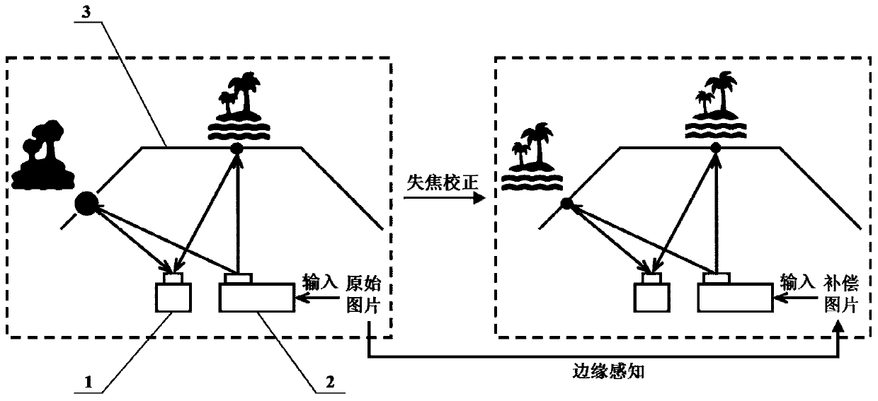
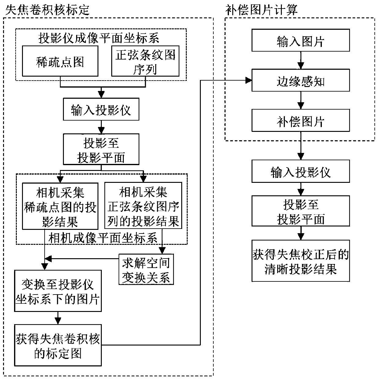
[0068] The specific implementation uses the projector-camera system to collect the projection results of the projector, such as figure 1 As shown, the projector-camera system includes: a camera 1, a projector 2, and a projection surface 3; the lens of the projector 2 and the lens of the camera 1 are both facing the projection surface 3; a special input image is input into the projector 2 to generate a light source to irradiate the projection surface On the surface 3, the camera 1 collects the projection result after the light source generated by the projector 2 is irradiated onto the projection surface 3 as the output image; combined with the special input image and the output image, the two steps of out-of-focus convolution kernel calibration and compensation image calculation are sequentially performed. Such as figure 2 As shown; the calculated compensatio...


PUM


Abstract

The invention discloses a projector out-of-focus correction method based on edge perception. According to the method, a projector-camera system is adopted, and a lens of a projector and a lens of a camera face the projection surface; inputting the special input image into a projector, projecting and irradiating the special input image onto a projection surface, and acquiring a projection result projected and irradiated onto the projection surface by the projector as an output image by a camera; and performing out-of-focus convolution kernel calibration by using the special input image and theoutput image to obtain a compensation picture, and performing correction compensation on the to-be-projected picture of the projector by taking the compensation picture as the input of the projector to obtain a clear projection result after out-of-focus compensation. The physical focal length of the projector does not need to be adjusted; according to the technical scheme, the clearness of the out-of-focus projection result of the projector can be realized only by processing the original picture input into the projector, the requirements of using the projector in complex application scenes such as thermal out-of-focus and large-amplitude height change of the projection surface of the projector can be met, and the applicability of the projector equipment is expanded to a certain extent.

Description

technical field [0001] The invention relates to the field of projection equipment, in particular to a method for improving the imaging quality of a projector, and in particular to an edge-sensing-based method for correcting the defocus of a projector. Background technique [0002] Projection equipment has a wide range of applications in the fields of video projection, slide presentation, virtual reality, etc. In the above-mentioned applications, the image of the projector on the projection surface is often blurred, which affects the user experience. The reasons for the blurring mainly include the following two aspects: First, when the projection surface is flat and the projection surface is perpendicular to the projection direction , the blurring phenomenon is mainly caused by thermal defocusing. Specifically, since the projector light source is a high-power device with high heat generation, the imaging components including the projector lens will be affected by thermal exp...

Claims


Application Information

Patent Timeline
IPC IPC(8): G06T7/80G03B21/14
CPCG06T7/80G03B21/142
Inventor 何再兴李沛隆赵昕玥
Owner ZHEJIANG UNIV
Why Eureka
Try Eureka