Elastic deployable helical antenna mechanism

A helical antenna and elastic technology, which is applied in the field of elastic expandable helical antenna mechanisms, can solve the problems of large volume of low-frequency antennas, and achieve the effects of large expansion ratio, small size and simple structure.

Active Publication Date: 2020-06-19
HARBIN INST OF TECH
View PDF4 Cites 1 Cited by
  • Summary
  • Abstract
  • Description
  • Claims
  • Application Information

AI Technical Summary

Problems solved by technology

[0004] The purpose of the present invention is to provide an elastic expandable helical antenna mechanism for the problem of large volume of existing low-frequency antennas

Method used


Image

  • Elastic deployable helical antenna mechanism
  • Elastic deployable helical antenna mechanism
  • Elastic deployable helical antenna mechanism

Examples


specific Embodiment approach 1

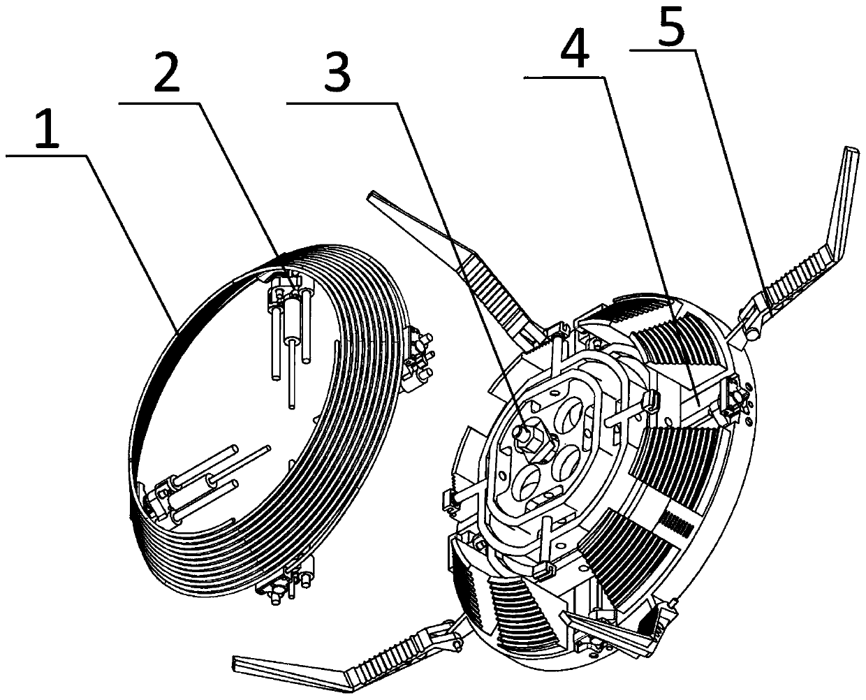
[0029] Specific implementation mode one: refer to figure 1 Describe this embodiment in detail. An elastically expandable helical antenna mechanism described in this embodiment includes: an antenna body 1 and a support base 4;

[0030] The support seat 4 includes a cylindrical shaft 4-1 and a fixed sleeve 4-2, the support seat 4 is processed with a groove 4-4, the cylindrical shaft 4-1 is arranged at the center of the support seat 4, and the cylindrical The axis of the shaft 4-1 is perpendicular to the support seat 4, the fixed sleeve 4-2 is set on the outside of the cylindrical shaft 4-1, the support seat 4 is provided with four grooves 4-4, and the support seat 4 A plurality of pressing devices 5 are arranged in the circumferential direction, and the support base 4 is also provided with four moving devices 2 in the circumferential direction, and the moving devices 2 are arranged in the groove 4-4, and the cylindrical shaft 4-1 is close to the support Seat 4 is processed with...

specific Embodiment approach 2

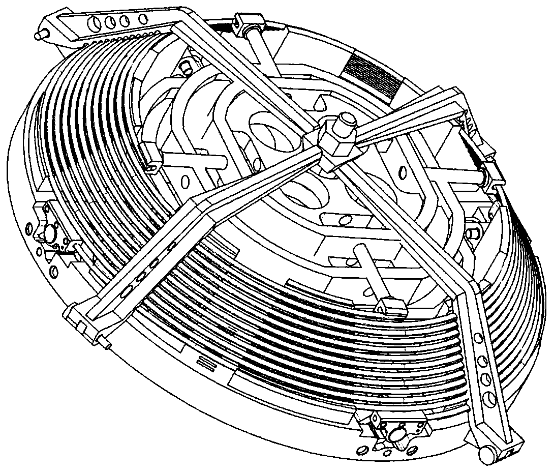
[0038] Specific embodiment 2: This embodiment is a further description of specific embodiment 1. The difference between this embodiment and specific embodiment 1 is that there are multiple auxiliary support plates 6, and the fixing clip 7 on one of the auxiliary support plates 6 It is fixedly connected with one end of the helical antenna; the other auxiliary support plates 6 are arranged between the auxiliary support plate 6 and the support seat 4, and the fixing clips 7 on the other auxiliary support plates 6 hold the helical antenna.

specific Embodiment approach 3

[0039] Embodiment 3: This embodiment is a further description of Embodiment 1. The difference between this embodiment and Embodiment 1 is that the compression support 5-1 and the compression arm 5-2 are provided with antennas to fix groove.


PUM


Abstract

An elastic deployable helical antenna mechanism relates to the technical field of spaceflight equipment and equipment, and comprises an antenna body and a supporting seat in order to solve the problemof large size of an existing low-frequency antenna. The supporting seat comprises a cylindrical shaft and a fixed sleeve, a groove is formed in the supporting seat, the cylindrical shaft is arrangedin the center of the supporting seat, the axis of the cylindrical shaft is perpendicular to the supporting seat, the fixed sleeve sleeves the cylindrical shaft, four grooves are formed in the supporting seat, the supporting base is provided with a plurality of pressing devices in the circumferential direction. Four moving devices are further arranged on the supporting base in the circumferential direction. The moving device is arranged in the groove, a separation ring groove is formed in the cylindrical shaft close to the supporting seat, the pressing device comprises a pressing support and apressing arm 5-2, the moving device comprises a rotating block, a torsion spring, a first hinge, a sliding block, a guide rail and a moving sleeve 2-7, the memory alloy unlocking and releasing devicecomprises a memory alloy sleeve, two nuts and a pressing block, and four fixing clamps are arranged on the auxiliary supporting disc. The antenna mechanism has simple structure, the large fold-extension ratio and the small volume.

Description

technical field [0001] The invention relates to the technical field of aerospace equipment and equipment, in particular to an elastic expandable helical antenna mechanism. Background technique [0002] With the rapid development of space communication, earth observation, deep space exploration, and manned spaceflight, the demand for large-scale, lightweight, and high-geometric stability aerospace space agencies has become very urgent, but limited by the volume of the rocket fairing Due to the limitation of space, it is necessary to design a space folding mechanism with a large folding ratio. It is in a folded state during the launch stage, and it is unfolded into a working state after the spacecraft enters orbit. The design and related research of the space folding mechanism is one of the key fundamental issues in the development of the future aerospace industry. [0003] With the development of aviation technology, geological exploration began to combine with aviation tech...

Claims


Application Information

Patent Timeline
Patent Type & Authority Applications(China)
IPC IPC(8): H01Q1/08H01Q1/12H01Q1/36
CPCH01Q1/08H01Q1/1235H01Q1/36
Inventor 郭宏伟刘荣强张炳健邓宗全田志东史创
Owner HARBIN INST OF TECH
Why Eureka
Try Eureka