Check patentability & draft patents in minutes with Patsnap Eureka AI!

A kind of ir2110 drive circuit and method based on buck-boost converter

A technology of IR2110 and driving circuit, which is applied in the field of power management of satellite power system, which can solve the problems such as the inability of the converter, the high-side output of low level, and the inability to drive the high-side switch tube.

Active Publication Date: 2021-11-09
SHANGHAI INST OF SPACE POWER SOURCES
View PDF0 Cites 0 Cited by
  • Summary
  • Abstract
  • Description
  • Claims
  • Application Information

AI Technical Summary

Problems solved by technology

[0010] A typical IR2110 non-bootstrap drive circuit can normally drive the low-side switch and the high-side switch in the normally-off or modulating state, but cannot drive the high-side switch in the normally-on state, which will cause the converter to fail When starting in voltage mode, or starting in buck mode, the synchronous tube does not work
The reason for this defect is that the high-side output of IR2110 can normally follow and amplify the logic high-side input signal only after the first rising edge of its logic high-side input signal appears, otherwise the high-side output will be constant low level

Method used


Image

  • A kind of ir2110 drive circuit and method based on buck-boost converter
  • A kind of ir2110 drive circuit and method based on buck-boost converter
  • A kind of ir2110 drive circuit and method based on buck-boost converter

Examples


Embodiment Construction

[0041] The present invention will be further described below through specific embodiments in conjunction with the accompanying drawings. These embodiments are only used to illustrate the present invention, and are not intended to limit the protection scope of the present invention.

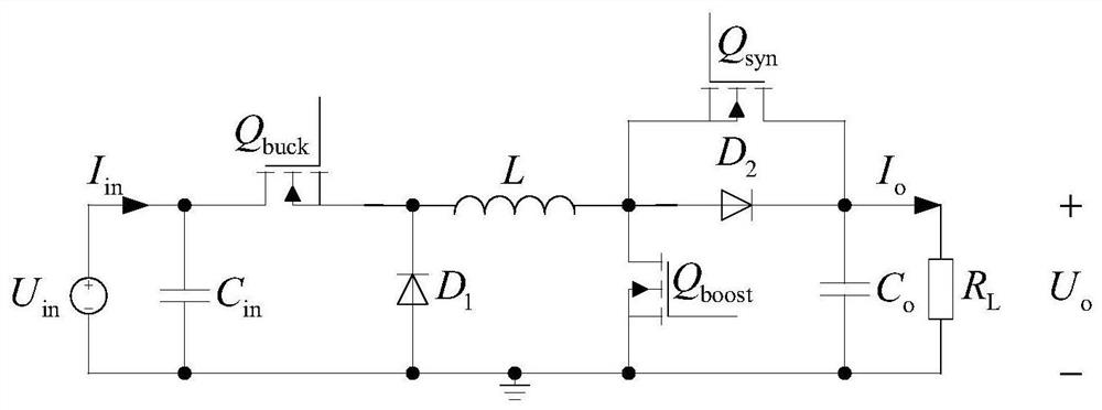
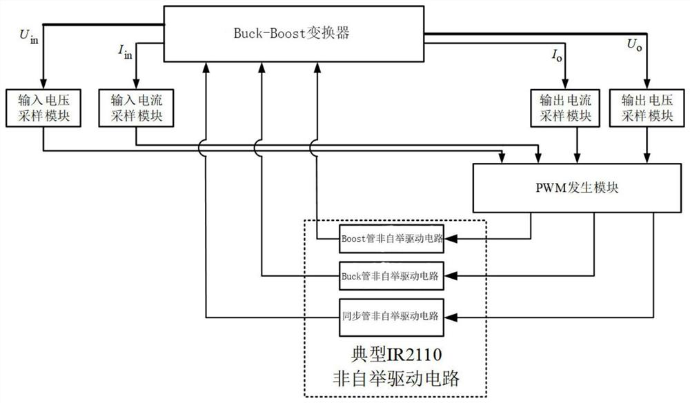
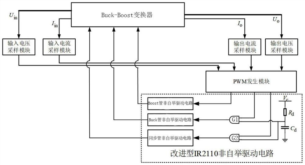
[0042] The present invention provides an IR2110 driving method based on a Buck-Boost converter, which includes: providing a delayed high-level signal; Phase AND: use the output signal after phase AND as the logic high side input signal of the IR2110 non-bootstrap drive circuit. In this preferred embodiment, the PWM drive signal of the Buck transistor and the synchronous transistor of the Buck-Boost converter is ANDed with the delayed high-level signal.

[0043]The present invention also provides a kind of IR2110 drive circuit based on Buck-Boost converter, it comprises: IR2110 non-bootstrap drive circuit; Auxiliary power supply; RC delay circuit, the input end of this RC delay circuit and describe...


PUM


Abstract

The invention discloses an IR2110 driving circuit based on a Buck-Boost converter and a method thereof. The driving method includes: providing a delayed high-level signal; Phase-AND of high-level signals; use the output signal after phase-AND as the logic high-side input signal of the IR2110 non-bootstrap drive circuit. The IR2110 drive circuit and method thereof based on the Buck-Boost converter proposed by the present invention introduce a delay time of T to the PWM drive signal of the high-side switch tube. delay The time delay, so that the duration of the high level after the converter is powered on exceeds T delay The PWM driving signal of the high-side switch can be powered on in the converter T delay A rising edge appears after a certain time to realize the normal driving of the high-side switch tube by IR2110. The drive circuit and the drive method proposed by the invention can ensure the normal startup of the converter and free switching between any working modes at any time.

Description

technical field [0001] The invention relates to the technical field of power management of a satellite power supply system, in particular to an IR2110 drive circuit based on a Buck-Boost converter and a method thereof. Background technique [0002] As the core component of the satellite, the main task of the power system is to provide high-quality, high-reliability continuous power for the entire satellite to meet the power requirements of the power load of the entire aircraft. [0003] With the continuous development of aerospace technology, people's requirements for space power systems are further improved. Satellite power systems not only need to achieve high power output, but also in order to improve system stability and energy efficiency, the topology of power converters and their control strategies are proposed. higher requirements. [0004] Because the satellite is affected by the light intensity during operation, the operating voltage of the solar panel changes grea...

Claims


Application Information

Patent Timeline
Patent Type & Authority Patents(China)
IPC IPC(8): H02M3/158H02M1/08H02M1/36
CPCH02M1/08H02M1/36H02M3/1582H02M1/0009
Inventor 林志松谢伟蓝建宇董梦雪夏晨泰邹小雨吴昕
Owner SHANGHAI INST OF SPACE POWER SOURCES
Features
  • R&D
  • Intellectual Property
  • Life Sciences
  • Materials
  • Tech Scout
  • Unparalleled Data Quality
  • Higher Quality Content
  • 60% Fewer Hallucinations
Learn More