
Camera module and electronic equipment

A camera module and lens technology, applied in TV, electrical components, color TV, etc., can solve the problem of poor heat dissipation effect of camera module and achieve good heat dissipation effect

Active Publication Date: 2020-06-19
VIVO MOBILE COMM CO LTD
View PDF7 Cites 5 Cited by
  • Summary
  • Abstract
  • Description
  • Claims
  • Application Information

AI Technical Summary

Problems solved by technology

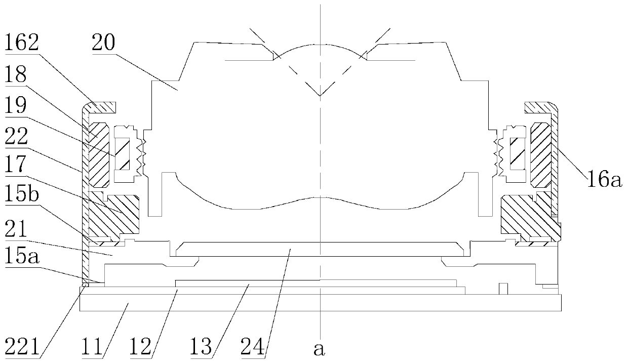
[0005] An object of the present invention is to provide a new technical solution for a camera module to solve the technical problem of poor heat dissipation of the camera module

Method used


Image

  • Camera module and electronic equipment
  • Camera module and electronic equipment
  • Camera module and electronic equipment

Examples


Embodiment Construction

[0019] Various exemplary embodiments of the present invention will now be described in detail with reference to the accompanying drawings. It should be noted that the relative arrangements of components and steps, numerical expressions and numerical values ​​set forth in these embodiments do not limit the scope of the present invention unless specifically stated otherwise.

[0020] The following description of at least one exemplary embodiment is merely illustrative in nature and in no way taken as limiting the invention, its application or uses.

[0021] Techniques, methods and devices known to those of ordinary skill in the relevant art may not be discussed in detail, but where appropriate, such techniques, methods and devices should be considered part of the description.

[0022] In all examples shown and discussed herein, any specific values ​​should be construed as exemplary only, and not as limitations. Therefore, other instances of the exemplary embodiment may have dif...


PUM


Abstract

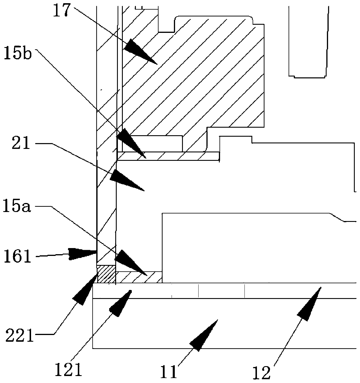
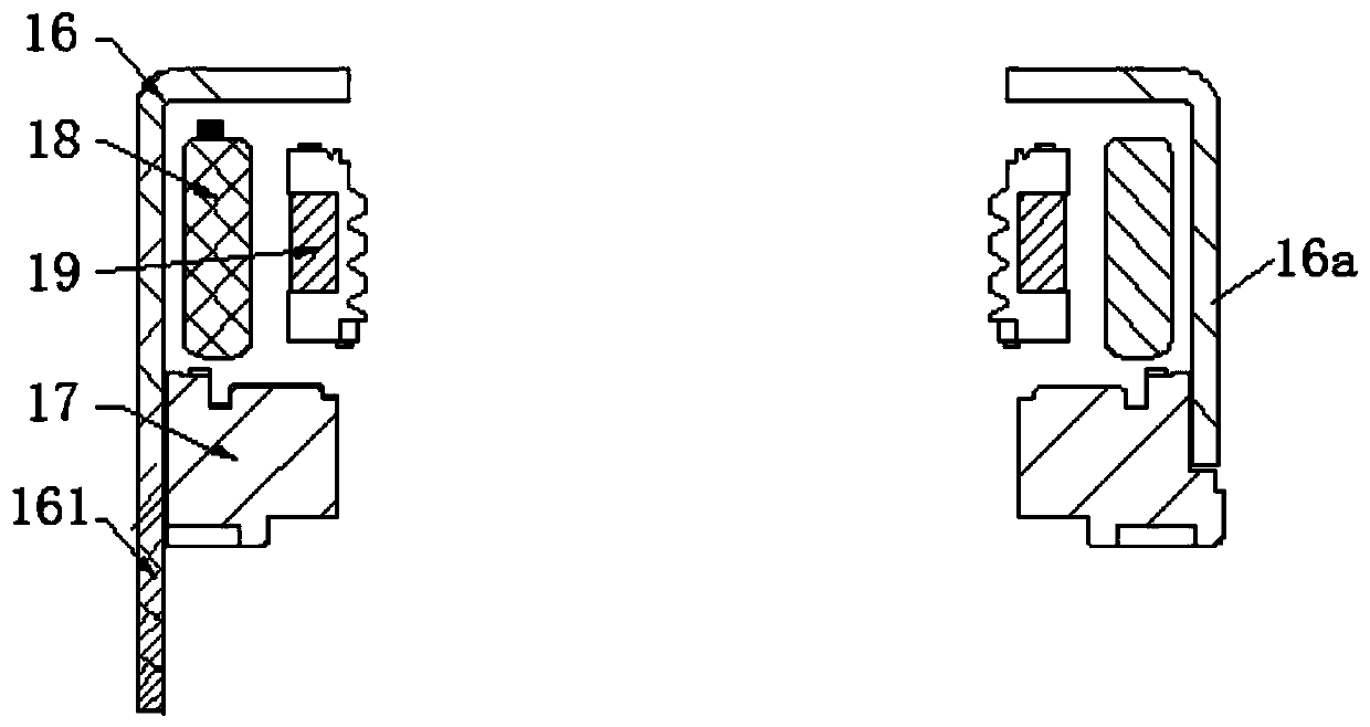
The embodiment of the invention discloses a camera module and electronic equipment. The camera module comprises a lens, a focusing device, an optical filter, a photosensitive chip, a substrate, a heatconduction part and a shell, a cavity is defined by the shell and the base plate together. The lens, the focusing device, the optical filter, the photosensitive chip and the heat conduction part arelocated in the cavity, wherein the lens is arranged in the focusing device, the heat conduction part is arranged on the substrate, the photosensitive chip is arranged on the heat conduction part, theoptical filter is located between the photosensitive chip and the lens, at least part of the shell forms a heat dissipation part, and the heat dissipation part is connected with the heat conduction part. The camera module has the characteristic of good heat dissipation effect.

Description

technical field [0001] Embodiments of the present invention relate to the technical field of camera devices, and more specifically, to a camera module and electronic equipment. Background technique [0002] Existing camera modules usually use a voice coil motor (VCM). The lens arranged on the voice coil motor is opposite to the photosensitive chip. The photosensitive chip is attached to the PCB board. The voice coil motor is connected with the PCB board. During use, the photosensitive chip heats up seriously. Especially the camera module with big bottom and high pixel. However, the heat dissipation effect of the PCB is poor, which causes the temperature of the photosensitive chip to rise, which affects the normal use of the camera module. [0003] In some solutions, heat dissipation materials, such as heat dissipation graphite and copper plates, are attached to the back of the substrate to improve the heat dissipation effect of the camera module. However, this method i...

Claims


Application Information

Patent Timeline
IPC IPC(8): H04N5/225G03B17/55G03B30/00
CPCG03B17/55H04N23/50
Inventor 刘峰
Owner VIVO MOBILE COMM CO LTD
Learn More