
A nail removal device for orthopedics

A technology of orthopedics and screw, which is applied in the field of medical devices, can solve the problems of difficulty in taking out bone nails, difficulty in taking out bone nails, and occurrence of rejection reactions, and achieve the effects of increasing stability, increasing strength, and increasing contact

Active Publication Date: 2021-03-26
施田宝
View PDF9 Cites 0 Cited by
  • Summary
  • Abstract
  • Description
  • Claims
  • Application Information

AI Technical Summary

Problems solved by technology

[0002] In orthopedic surgery, steel plates and bone nails are usually used to reset and fix the bone fragments at the fracture site, so that the dislocated bone fragments are closely connected again under the action of the steel plates and bone nails, and after a long period of postoperative growth, The broken bone fragments grow calluses and heal together again. The internal fixation needs to be removed 1-2 years after the operation to avoid rejection. The bone screws used include hollow bone screws, self-tapping bone screws, and non-self-tapping bone screws. Screws, etc., use the bone screw extractor to clamp the bone screw cap and rotate to take out the bone screw during the whole process of taking out. Small, easy to break the bone screw, it is difficult to take out the bone screw completely, and it is more difficult to take out the broken bone screw, and it is easy to cause re-injury at the fracture site; when the hollow bone screw is taken out, only the stress point acts on the bone screw cap It is easier to break the hollow bone screw; the currently used bone screw remover only fixes the fixing cap, which is prone to loosening and slipping during the removal process, making it difficult to remove the bone screw

Method used


Image

  • A nail removal device for orthopedics
  • A nail removal device for orthopedics
  • A nail removal device for orthopedics

Examples


Embodiment 1

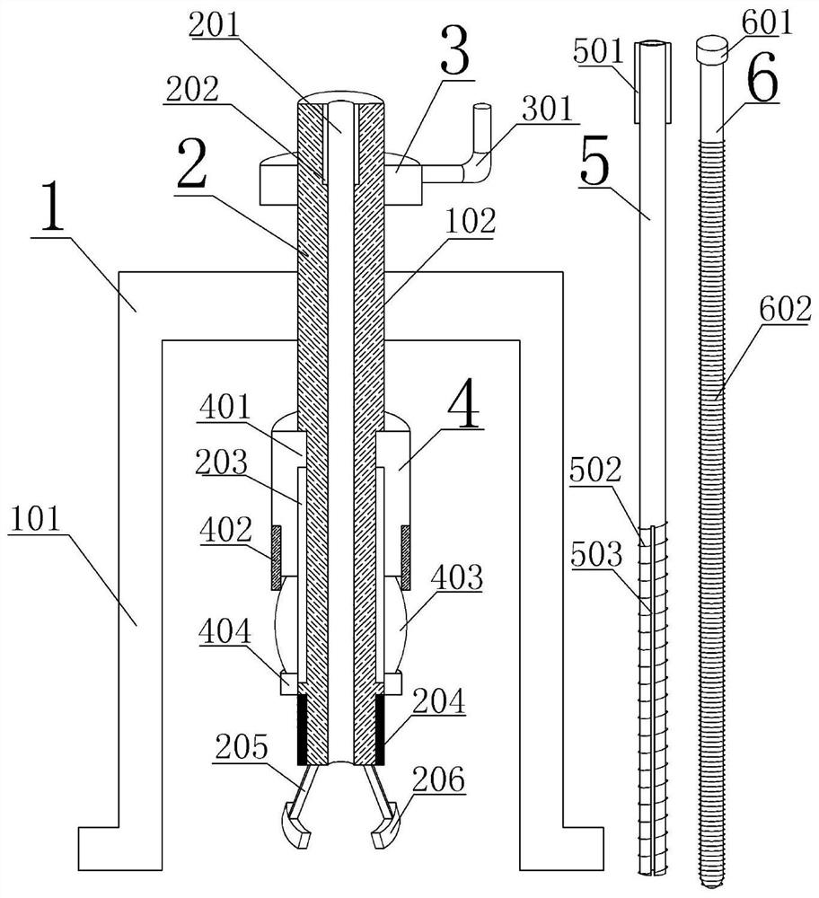
[0062] When the present invention is used as an orthopedic nail removal device, the specific application of the hollow bone screw is as follows: when in use, the bracket with legs can be used to make the nail removal device relatively stable at the corresponding position, and the rotating handle is turned to make the screw rod in the cylindrical hollow. The screw thread in the groove moves down to the corresponding position of the bone screw, clamps the clamping part on the bone screw cap, turns the screw sleeve to move down to control the relative movement of the connecting rod so that the clamping part clamps the bone screw cap, and spreads the sleeve The rod is inserted into the hollow bone screw from the channel of the screw rod, and a spreader sleeve rod of an appropriate length is selected according to the length of the hollow bone screw, so that the clamping strip at the end of the spreader sleeve rod is located in the vertical groove, and the spreader rod is inserted int...

Embodiment 2

[0065] The specific application of the present invention when used as an orthopedic nail taking device to take other solid bone screws is: when in use, the nail taking device can be relatively stably placed at the corresponding position by using the bracket with feet, and the rotating handle is turned to make the screw rod and the bracket contact each other. The screw thread in the cylindrical hollow groove moves the screw down to the corresponding position of the bone screw, clamps the clamping part on the bone screw cap, and turns the screw sleeve to move down to control the relative movement of the connecting rod so that the clamping part clamps the bone screw cap , turn the handle to move the screw up slowly to take out the bone screw. During the process of taking out the bone screw, after a section of the bone screw is taken out, unscrew the connecting sleeve and move the composite sleeve down along the chute, and turn the compression sleeve to move down to press the screw....


PUM


Abstract

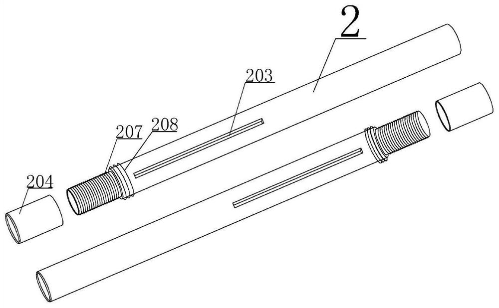
The invention discloses a nail taking device for the orthopedics department. The nail taking device comprises a support, a screw, a composite sleeve, a distraction loop bar and a distraction rod, wherein a plurality of supporting legs are arranged on the support, the screw is installed in the support, the screw is a hollow cylindrical pipe, vertical grooves are symmetrically formed in the inner wall of one end of the screw, a hollow screw head is arranged at the other end of the screw, a screw sleeve is installed on the screw head, connecting rods are symmetrically hinged to an end of the screw head, clamping pieces are arranged at the ends of the connecting rods, and connecting threads are arranged on the outer wall, connected with the screw head, of the screw; the composite sleeve is installed on the screw, protruding strips are installed in sliding grooves, and threads on the inner wall of a connecting sleeve are connected with the connecting threads in a matched mode; the distraction loop bar is mounted in the screw; and the distraction rod is installed in the distraction loop bar. By increasing acting force points acting on bone nails, the bone nails can be taken out more easily and are not prone to loosen, slip and break.

Description

technical field [0001] The invention relates to the technical field of medical devices, in particular to a nail removal device for orthopedics. Background technique [0002] In orthopedic surgery, steel plates and bone nails are usually used to reset and fix the bone fragments at the fracture site, so that the dislocated bone fragments are closely connected again under the action of the steel plates and bone nails, and after a long period of postoperative growth, The broken bone fragments grow calluses and heal together again. The internal fixation needs to be removed 1-2 years after the operation to avoid rejection. The bone screws used include hollow bone screws, self-tapping bone screws, and non-self-tapping bone screws. Screws, etc., use the bone screw extractor to clamp the bone screw cap and rotate to take out the bone screw during the whole process of taking out. Small, easy to break the bone screw, it is difficult to take out the bone screw completely, and it is mor...

Claims


Application Information

Patent Timeline
Patent Type & Authority Patents(China)
IPC IPC(8): A61B17/92
CPCA61B17/8875A61B17/92
Inventor 施田宝
Owner 施田宝
Learn More