
Automatic spectacle frame welding machine

An automatic welding machine and spectacle frame technology, applied in welding equipment, welding equipment, laser welding equipment, etc., can solve the problems of low production efficiency and inability to continue automatic production, and achieve the effect of increasing processing efficiency and continuous automatic processing

Pending Publication Date: 2020-06-23
温州艾特科智能科技有限公司
View PDF0 Cites 2 Cited by
  • Summary
  • Abstract
  • Description
  • Claims
  • Application Information

AI Technical Summary

Problems solved by technology

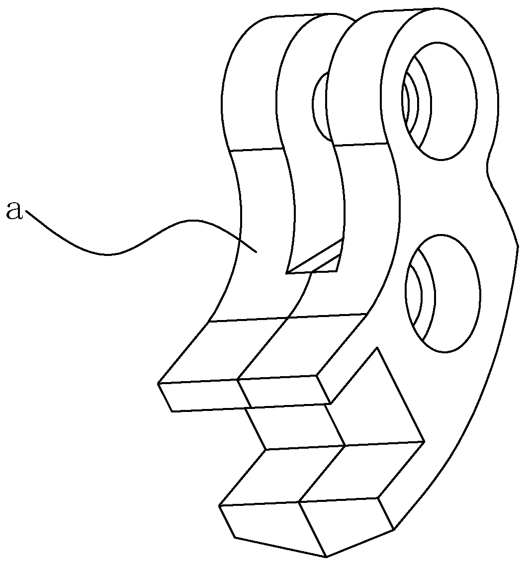
[0002] During the processing of glasses, it is necessary to combine the lens ring with the lock block (such as figure 1 As shown, that is, the part of the hinged structure located on the mirror ring) is fixedly connected, and the commonly used connection method is welding, and often requires solder paste, welding, cutting and other processes, and after welding a single mirror ring, it is necessary to The two mirror rings that are welded with lock blocks are then welded by connecting strips, and then the nose pads are welded to form a mirror frame. However, the existing welding process of the mirror frame is often performed on multiple machines. Processing, production efficiency is low, and continuous automatic production cannot be carried out

Method used


Image

  • Automatic spectacle frame welding machine
  • Automatic spectacle frame welding machine
  • Automatic spectacle frame welding machine

Examples


Embodiment Construction

[0034] The following will clearly and completely describe the technical solutions in the embodiments of the present invention with reference to the accompanying drawings in the embodiments of the present invention. Obviously, the described embodiments are only some, not all, embodiments of the present invention. Based on the embodiments of the present invention, all other embodiments obtained by persons of ordinary skill in the art without making creative efforts belong to the protection scope of the present invention.

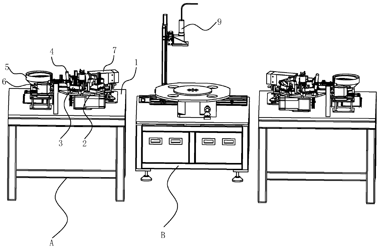
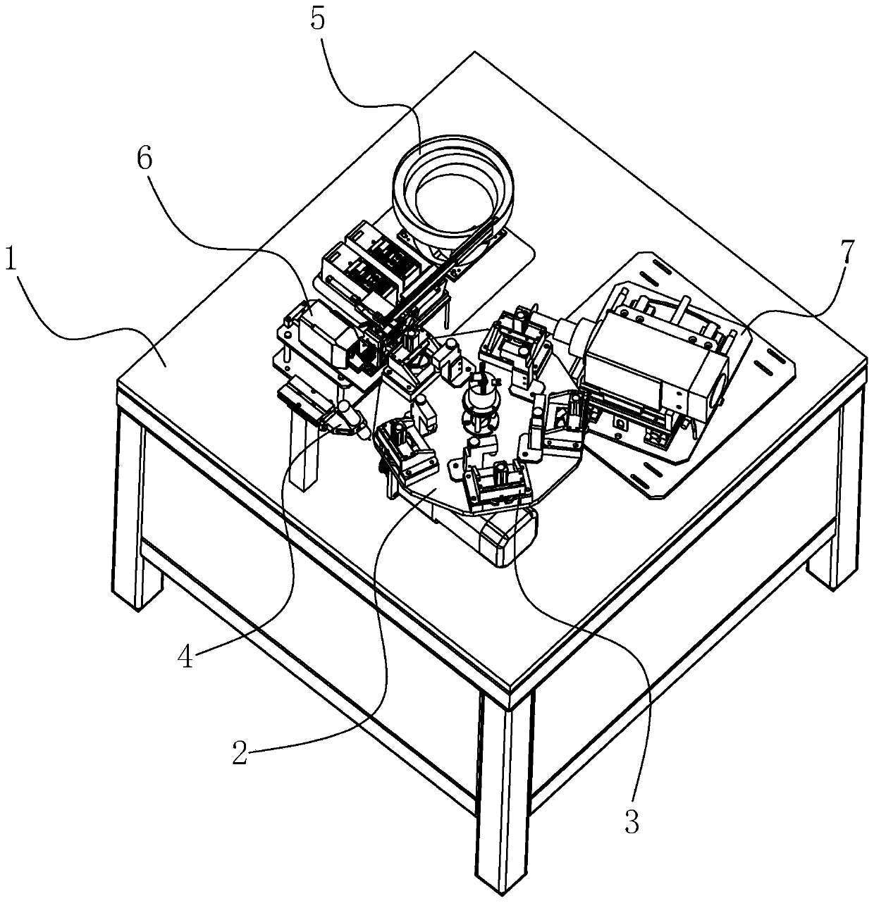
[0035] Such as Figure 1-16 As shown, an automatic welding machine for spectacle frames includes two sets of symmetrically arranged lens ring welding devices A and a welding station B. The lens ring welding device A includes a frame 1 and a turntable 2 arranged on the frame 1, It also includes: a feeding assembly 3, which is arranged on the turntable 2 and has at least one set, and it includes a mirror ring mold base 8 for accommodating the mirror ring b and c...


PUM


Abstract

The invention discloses an automatic spectacle frame welding machine. The welding machine comprises two sets of spectacle ring welding devices which are symmetrically arranged and a welding table, wherein each spectacle ring welding device comprises a machine frame, a rotary table arranged on the machine frame and a feeding assembly, and at least one set of feeding assembly is arranged on the rotary table; and each feeding assembly comprises a spectacle ring mold seat used for containing spectacle rings and a positioning device capable of fixing the spectacle rings on the spectacle ring mold seat, the spectacle ring mold seat is provided with an abutting block capable of pushing a welding portion of the spectacle ring, and each feeding assembly further comprises a spot welding assembly, avibration plate, a welding assembly, a cutting assembly and a spectacle frame mold seat. According to the automatic spectacle frame welding machine, the spectacle ring welding devices and the weldingtable are arranged, so that a plurality of procedures of spectacle frame processing can be carried out on one machine, so that continuous automatic processing of the spectacle rings and spectacle frames can be realized, and the machining efficiency is greatly improved.

Description

technical field [0001] The invention relates to the technical field of glasses equipment, in particular to an automatic welding machine for glasses frames. Background technique [0002] During the processing of glasses, it is necessary to combine the lens ring with the lock block (such as figure 1 As shown, that is, the part of the hinged structure located on the mirror ring) is fixedly connected, and the commonly used connection method is welding, and often requires solder paste, welding, cutting and other processes, and after welding a single mirror ring, it is necessary to The two mirror rings that are welded with lock blocks are then welded by connecting strips, and then the nose pads are welded to form a mirror frame. However, the existing welding process of the mirror frame is often performed on multiple machines. Processing, production efficiency is low, can not carry out continuous automatic production. Contents of the invention [0003] The object of the present...

Claims


Application Information

Patent Timeline
Patent Type & Authority Applications(China)
IPC IPC(8): B23K26/21B23K26/70B23K37/04B23D79/00B23K26/00
CPCB23D79/00B23K26/0093B23K26/21B23K26/702B23K37/0443
Inventor 胡加一
Owner 温州艾特科智能科技有限公司
Learn More