Pile bottom grouting device and use method thereof

A grouting device and pile bottom technology, applied in sheet pile wall, construction, infrastructure engineering and other directions, can solve the problems of easy blockage of grouting pipe, low grouting pressure, and unsatisfactory grouting volume, and achieve cost Inexpensive, solve blockage, easy to obtain effect

Pending Publication Date: 2020-06-23
YUNNAN CONSTR INVESTMENT FIRST SURVEY & DESIGN CO LTD
View PDF0 Cites 1 Cited by
  • Summary
  • Abstract
  • Description
  • Claims
  • Application Information

AI Technical Summary

Problems solved by technology

[0004] Aiming at the above-mentioned problems existing in the prior art, the present invention provides a pile bottom grouting device and its use method. The device uses a rubber check sleeve to separate the poured concrete and the grouting pipe. The grout will not be poured into the grouting pipe, and the grout will not flow back during grouting, which provides a guarantee for the smoothness of subsequent grouting, and solves the problem of easy blockage of the grouting pipe when grouting at the pile end, the grouting volume not meeting the requirements, and the grouting pressure small problem

Method used


Image

  • Pile bottom grouting device and use method thereof

Examples


Embodiment Construction

[0022] The following will clearly and completely describe the technical solutions in the embodiments of the present invention with reference to the accompanying drawings in the embodiments of the present invention. Obviously, the described embodiments are only some, not all, embodiments of the present invention. Based on the embodiments of the present invention, all other embodiments obtained by persons of ordinary skill in the art without creative efforts fall within the protection scope of the present invention.

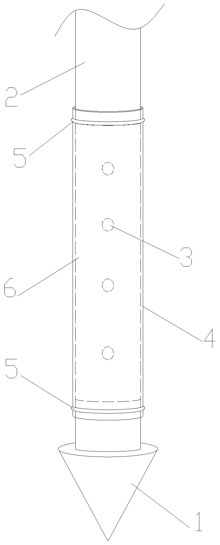
[0023] refer to figure 1 As shown, a pile bottom grouting device includes a cone head 1, a grouting pipe 2 and a rubber check sleeve 4, the cone head 1 is a stainless steel cone head, and the cone head 1 is welded to the bottom end of the grouting pipe 2; The grouting pipe 2 is a steel pipe with an inner diameter of 50 mm. The wall thickness of the steel pipe is 3.5 mm. Grouting holes 3 are evenly distributed on both sides of the bottom of the grouting pipe 2. The ...


PUM


Abstract

The invention discloses a pile bottom grouting device and a use method thereof. The pile bottom grouting device comprises a cone head, a grouting pipe and a rubber non-return sleeve. The cone head isfixed to the bottom end of the grouting pipe, slurry through holes are evenly distributed in the two sides of the bottom of the grouting pipe, the pipe section, provided with the slurry through holes,of the grouting pipe is a grouting section, the rubber non-return sleeve wraps the grouting section, the inner wall of the rubber non-return sleeve covers the surfaces of the slurry through holes, and the upper end and the lower end of the rubber non-return sleeve are fixed to the grouting pipe through fastening devices. The use method of the pile bottom grouting device includes the steps that the position of the grouting pipe is adjusted, the grouting pipe is fixed, a reinforcement cage is hung, concrete is poured, and pile body soil mass is reinforced. According to the device, the poured concrete and the grouting pipe are separated through the rubber non-return sleeve, slurry cannot be injected into the grouting pipe during pile body concrete pouring, the slurry cannot flow back duringgrouting, the smoothness of following slurry pressing is guaranteed, and the problems that during pile end grouting, the grouting pipe is easily blocked, the grouting amount does not meet the requirements, and the grouting pressure is small are solved.

Description

technical field [0001] The invention relates to the field of geotechnical engineering construction devices, in particular to a pile bottom grouting device and a use method thereof. Background technique [0002] Bored cast-in-situ pile refers to a pile formed by drilling a pile hole with a drilling machine, hanging a steel cage in the hole, and pouring concrete in the hole. Due to its advantages of no vibration, no soil extrusion, low noise, and suitable for use in densely built urban areas during construction, the construction technology of bored piles has been widely used in construction. [0003] After a certain period of time after the cast-in-situ pile is piled, it is necessary to inject cement slurry through the grouting conduit preset in the pile body and the pile bottom grouting valve connected to it. The nearby soil is dense and produces a "bottom expansion" effect, which strengthens the soil (including sediment and mud) at the bottom of the pile, thereby increasing...

Claims


Application Information

Patent Timeline
Patent Type & Authority Applications(China)
IPC IPC(8): E02D15/04E02D5/62
CPCE02D5/62E02D15/04
Inventor 贾荣谷刘克文董天雷普国泰翁彦梅陈茹梅关艳丽马贺雅王锦晔屈金华业文涛李国林
Owner YUNNAN CONSTR INVESTMENT FIRST SURVEY & DESIGN CO LTD
Why Eureka
Try Eureka