
Infection source isolation device and isolation method

A technology for isolating devices and sources of infection, applied in the field of isolation devices for sources of infection, to achieve the effects of avoiding cross-infection, easy installation, and convenient promotion and application

Pending Publication Date: 2020-06-23
SUN YAT SEN UNIV CANCER CENT +1
View PDF0 Cites 1 Cited by
  • Summary
  • Abstract
  • Description
  • Claims
  • Application Information

AI Technical Summary

Problems solved by technology

At present, there is no household emergency device for isolating the source of infection on the market

Method used


Image

  • Infection source isolation device and isolation method
  • Infection source isolation device and isolation method

Examples


Embodiment 1

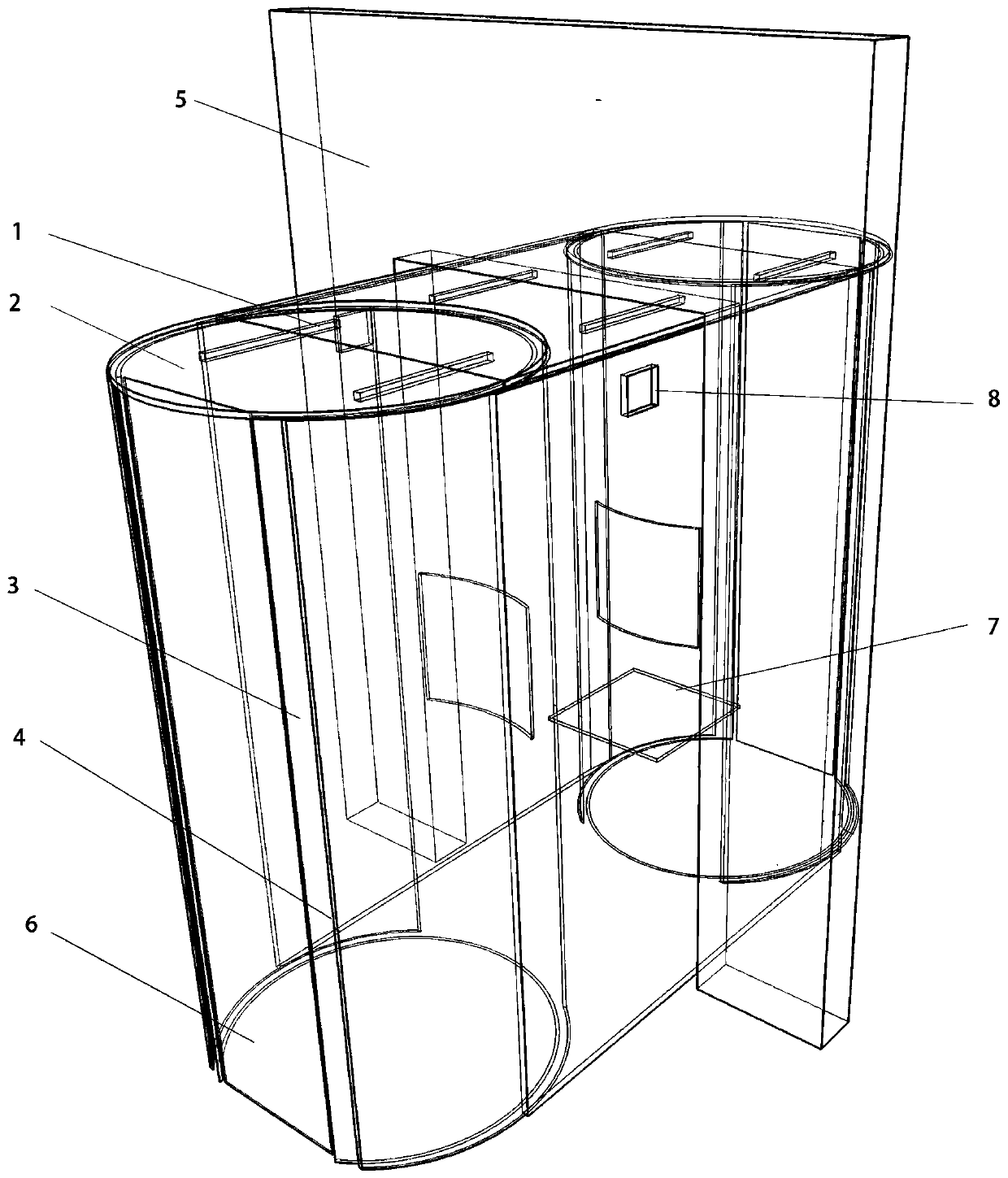
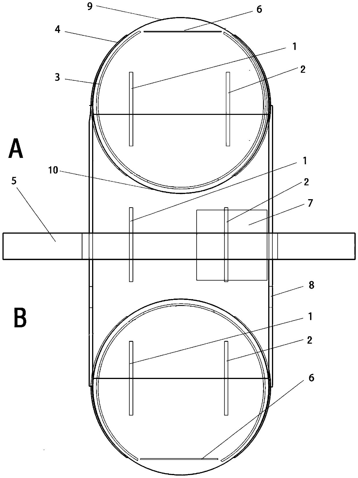
[0026] An infection source isolation device, which can be used in the living room. The device is placed on the door frame of the living room to divide the home into a polluted area, a clean barrier area, and a clean area. The polluted area is the activity area of ​​infected persons or suspected infected persons. The clean area is the activity area of ​​uninfected personnel. The device acts as a clean barrier area to fully isolate the clean area from the polluted area to avoid cross-infection. It is also used to deliver daily necessities to the isolated personnel during the isolation period. The device is easy to install and can be installed by the user. It can effectively and timely isolate the source of infection and protect the susceptible population.

[0027] The device includes a device body, such as figure 1 and figure 2 As shown, the device body is composed of a cuboid cavity, an outer cylinder cavity 4 and an inner cylinder cavity 3 at both ends of the cuboid. Both t...

Embodiment 2

[0040] An infection source isolation device, the device includes a device body, the device body is composed of a closed foldable waterproof, air-tight cloth or plastic cover and a built-in detachable tubular support frame, which is supported by the detachable tubular support frame during use. Foldable waterproof, air-tight cloth or plastic cover to form a cuboid cavity structure. Both ends of the cuboid cavity are provided with a horizontally folded inlet and outlet, and the horizontally folded inlet and outlet are made of waterproof, air-tight cloth or plastic and a two-way zipper. One end of the cuboid cavity is provided with two ventilation windows, which can adopt a laminar layer structure similar to an N95 mask, so as to prevent bacteria, viruses and other microorganisms inside the device from entering the clean area while ensuring the ventilation of the ventilation windows.

[0041] The device also includes ultraviolet lamps for disinfection and lighting lamps for illumi...


PUM


Abstract

The invention relates to an infection source isolation method. A contaminated area containing an infection source is isolated from a clean area not containing the infection source to avoid cross infection. The method comprises the following steps that S1, a clean barrier area is created at the junction of the contaminated area and the clean area, the contaminated area is completely isolated from the clean area by the clean barrier area, an inlet / outlet communicating with the contaminated area is formed in one end of the clean barrier area, an inlet / outlet communicating with the clean area is formed in the other end, and in an initial state, the inlet / outlet of the clean area and the inlet / outlet of the contaminated area are closed; and S2, an ultraviolet lamp is arranged in the clean barrier area for continuous disinfection sterilization, a clean area channel and a contaminated area channel are opened alternatively, it is guaranteed that objects in the clean area and objects in the contaminated area can be isolated from each other during communication, and cross infection is avoided. The invention also relates to an infection source isolation device which is simple in structure andeasy and convenient to install, can be installed and used by a user himself / herself, and is convenient to apply and popularize.

Description

technical field [0001] The invention belongs to the field of isolation and protection, in particular to an isolation device and isolation method for an infection source. Background technique [0002] Because infectious diseases transmitted by the respiratory tract, such as atypical pneumonia (SARS) and new coronavirus pneumonia, are highly contagious, it is often easy to infect family members with mild symptoms or early stage patients. Therefore, when a source of infection or a suspected source of infection that needs to be isolated is found, such as close contact with patients, patients with early symptoms, and patients with mild symptoms, there is an urgent need for isolation devices for household or local applications, which can achieve isolation at an early stage and effectively control infection. [0003] Respiratory infectious diseases such as SARS and novel coronavirus pneumonia have obvious family clustering, and often one member of a family becomes ill. Because ther...

Claims


Application Information

Patent Timeline
IPC IPC(8): E04H1/12A61L2/10
CPCE04H1/125E04H1/1277A61L2/10
Inventor 符立梧王仁友
Owner SUN YAT SEN UNIV CANCER CENT
Learn More