
Waste rock and tailing sand cooperative cementing filling method

A technology of cemented filling and tailings, which is applied in the direction of filling, earth square drilling, safety devices, etc., which can solve the problems of unconsolidated loose waste rock bodies, large permeability differences, waste rock mixed with ore, etc., and achieve simplified waste rock Filling work, reducing ore dilution, good isolation effect

Active Publication Date: 2020-06-23
锡林郭勒盟山金阿尔哈达矿业有限公司
View PDF7 Cites 1 Cited by
  • Summary
  • Abstract
  • Description
  • Claims
  • Application Information

AI Technical Summary

Problems solved by technology

At present, the waste rock + tailing sand cemented filling body formed by this process method has the following problems in the construction process: the filled waste rock is formed after rock drilling and blasting, and the block size is uneven. However, due to the large difference in permeability under natural accumulation, there are loose waste rocks that cannot be consolidated locally, especially in the bottom layer of the pile, which makes it difficult for the second-step mining in the later stage
Stope backfilling waste rocks are mainly shoveled to the stope by forklifts or trucks, and the waste rocks near the two sides of the stope are required to have a natural repose angle profile, but it is difficult to control the site construction, and it is easy to cause waste rocks to be mixed into the ore during the second-step mining , resulting in secondary depletion of ore

Method used


Image

  • Waste rock and tailing sand cooperative cementing filling method
  • Waste rock and tailing sand cooperative cementing filling method
  • Waste rock and tailing sand cooperative cementing filling method

Examples


Embodiment Construction

[0039] In order to make the objects and advantages of the present invention clearer, the present invention will be further described below in conjunction with the examples; it should be understood that the specific examples described here are only for explaining the present invention, and are not intended to limit the present invention.

[0040]Preferred embodiments of the present invention are described below with reference to the accompanying drawings. Those skilled in the art should understand that these embodiments are only used to explain the technical principle of the present invention, and are not intended to limit the protection scope of the present invention.

[0041] It should be noted that, in the description of the present invention, terms such as "upper", "lower", "left", "right", "inner", "outer" and other indicated directions or positional relationships are based on the terms shown in the accompanying drawings. The direction or positional relationship shown is o...


PUM

PropertyMeasurementUnit
Densityaaaaaaaaaa
Densityaaaaaaaaaa

Abstract

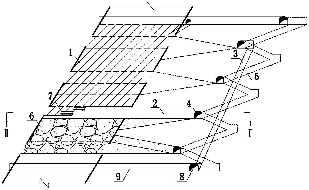
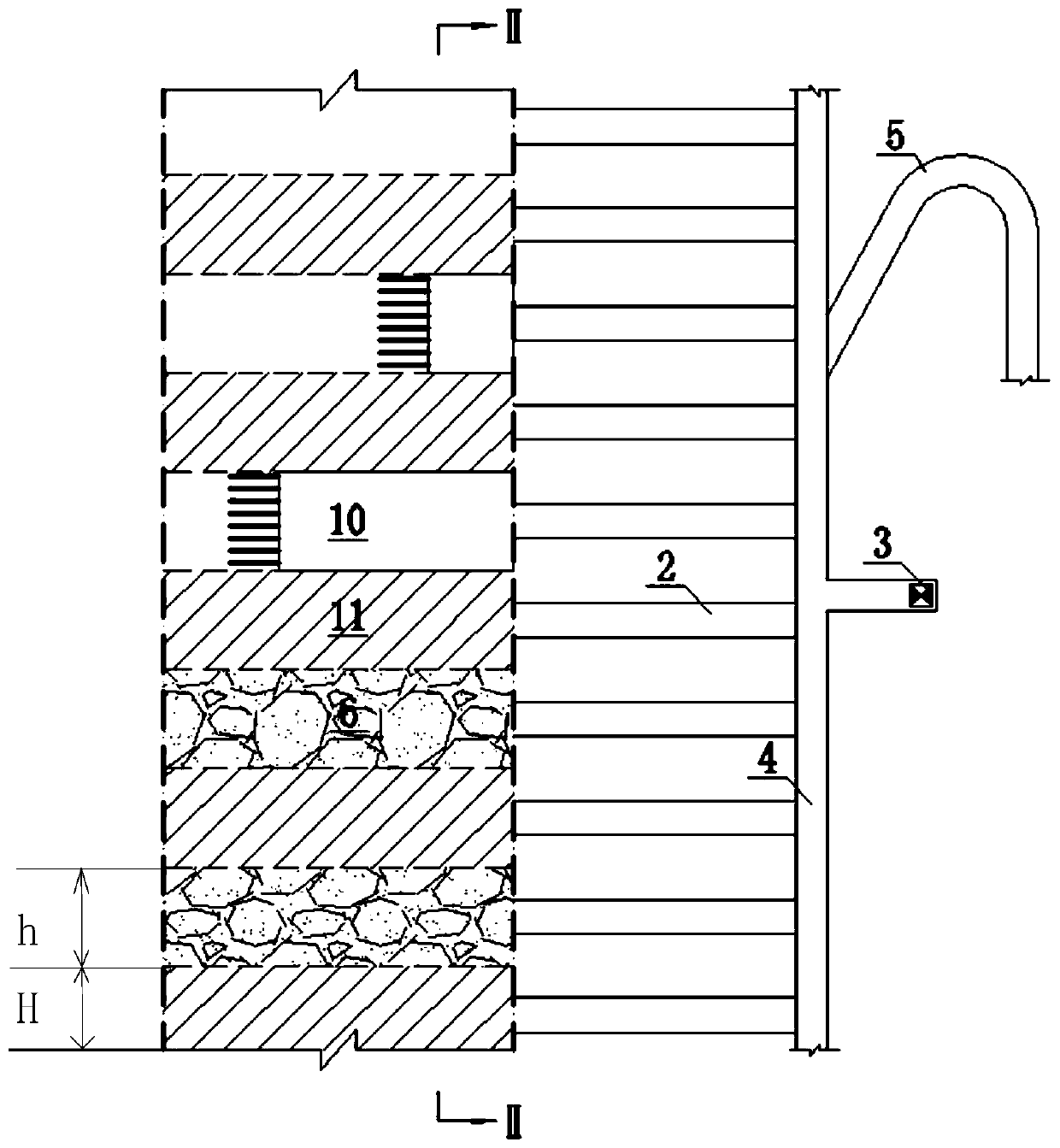
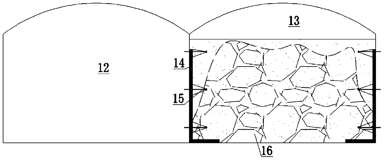
The invention relates to a waste rock and tailing sand cooperative cementing filling method. The waste rock and tailing sand cooperative cementing filling method is characterized by comprising the following steps that step1, a stope adopts a form of extracorporeal ramp mining and is boosted by adopting a sequence stoping method of separating one and mining one along an ore body, after stope stoping is finished, an empty area is formed, the stope is cleaned, and stope cleaning comprises cleaning of helping wall pumice and helping foot residue; step2, a chain link fence is set up and is laid behind a helping wall, and iron wires are adopted to be connected with anchor rod end portions to be used for isolating waste rocks and the ore body; step3, the waste rocks are stacked, the excavation working face waste rocks are dumped to the stope by adopting a forklift, the helping foot chain link fence is compressed when stacking is performed, and then normal stacking is performed; step4, tailingsand cementing filling is performed, waste rock stacking is stopped when being performed to a distance from the preset filling height, filling pipelines are laid, and graded tailing sand cementing filling is performed; and step5, filling curing is performed, and after the to-be-filled body strength reaches the construction requirements, stoping operations of an adjacent two-step mining stope arestarted.

Description

technical field [0001] The invention relates to the technical field of mine excavation, in particular to a method for collaborative cementation and filling of waste rock tailings. Background technique [0002] Commonly used mining methods in underground metal mines are divided into three categories: empty field method, caving method and filling method. Empty field method and caving method. At present, with the maturity of filling technology, the grade of mining resources declines year by year, the potential safety hazards formed by empty areas are highlighted, and the surface mining subsidence is affected, the application of empty field method and caving method is restricted. The mining method has also developed from the initial waste rock filling and water sand filling to the current graded tailings cemented filling, full tailing paste filling, block stone cemented filling, and waste filling from other industries. [0003] The most commonly used filling mining method is th...

Claims


Application Information

Patent Timeline
IPC IPC(8): E21F15/00E21F15/04
CPCE21F15/005E21F15/04
Inventor 马明辉李红旗周亚博张恒超刘兴宇沙鸥赵学平魏志远刘也柏杨侯荣翰张佰通
Owner 锡林郭勒盟山金阿尔哈达矿业有限公司
Learn More