Test equipment of truck or automobile clutch bearings

A test equipment and clutch technology, applied in the direction of mechanical bearing testing, etc., to achieve the effect of simple structure, reliable test and convenient operation

Inactive Publication Date: 2020-06-23
C&U CO LTD +1
View PDF5 Cites 0 Cited by
  • Summary
  • Abstract
  • Description
  • Claims
  • Application Information

AI Technical Summary

Problems solved by technology

[0003] At present, because the requirements for the speed of trucks or cars are getting higher and higher, the speed of the bearings is also getting higher and higher. According to the market demand for car clutch bearings and truck clutch bearings, the speed requirements are up to 12000rpm and the maximum load is 12KN. One spindle cannot take care of both. In terms of the loading method, there are requirements for the time of bearing separation and contact, as well as the loading rate, and the ambient temperature of the test needs to be controlled. It is urgent to design a test equipment that meets the above requirements.

Method used


Image

  • Test equipment of truck or automobile clutch bearings
  • Test equipment of truck or automobile clutch bearings
  • Test equipment of truck or automobile clutch bearings

Examples


Embodiment Construction

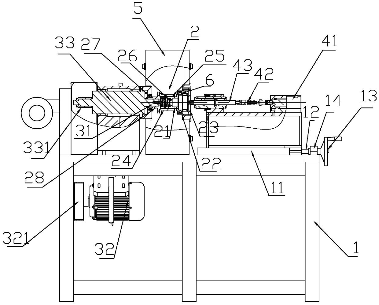
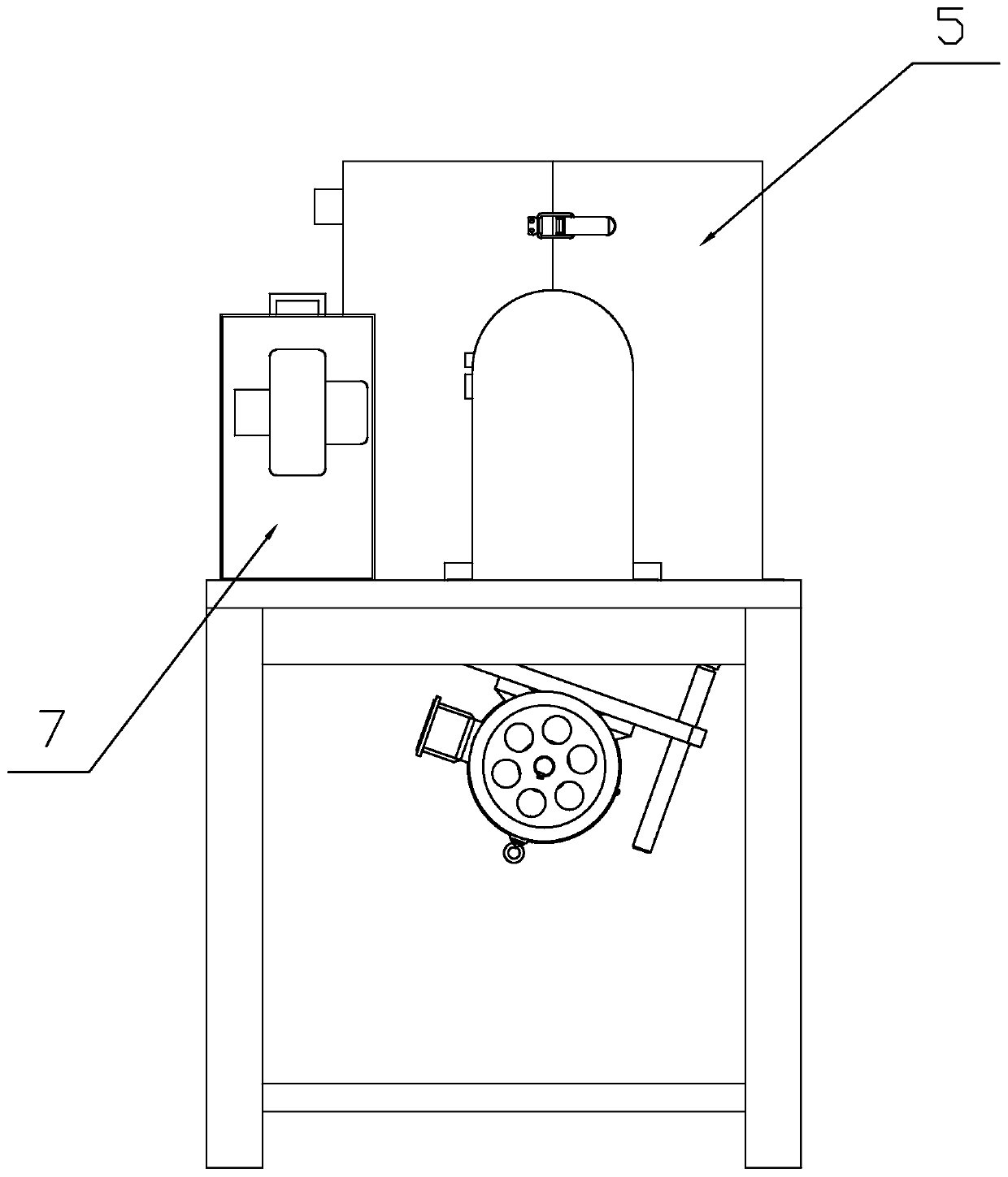
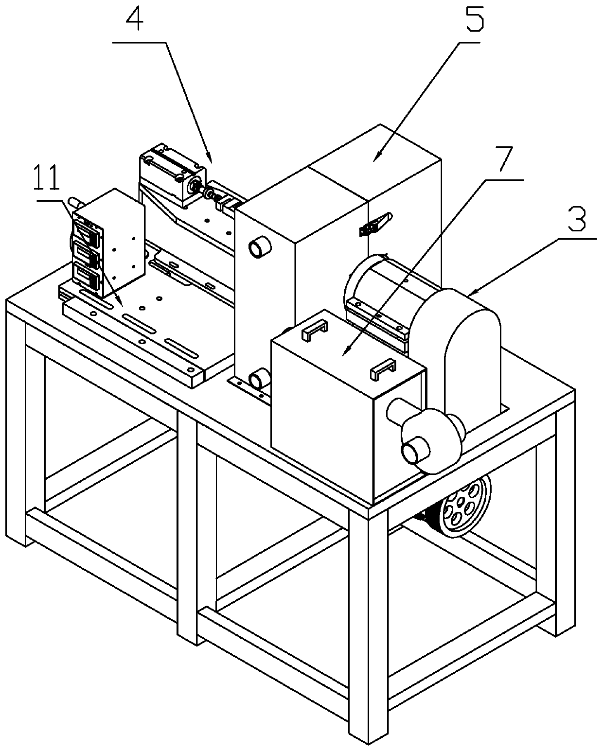
[0023] Specific examples of the present invention Figure 1-3 As shown, a truck or automobile clutch bearing test equipment includes a frame 1. The frame 1 is equipped with an imitation clutch 2, a driving mechanism 3, a release bearing action operating mechanism 4, and a temperature control box 5. The imitation clutch 2 is placed in a temperature control box 5. The imitation clutch 2 includes a rotating loading tool and a pre-tightening force mechanism. The pre-tightening force mechanism is located between the rotating loading tool and the drive mechanism 3. The drive mechanism 3 The output end 31 is connected to the rotary loading tooling through a pretensioning mechanism, the rotary loading tooling includes a simulated flywheel 21 connected with the pretensioning mechanism, a clutch disc 22 for mounting the bearing 6 to be tested, and a release bearing action operating mechanism 4 The connecting transition disc 23, the bearing 6 to be tested is mounted on the clutch disc 22,...


PUM


Abstract

The invention discloses test equipment of a truck or automobile clutch bearing. A frame is included. An imitation clutch, a driving mechanism, a release bearing action operating mechanism and a temperature control box are mounted on the frame; the imitation clutch is arranged in the temperature control box; the imitation clutch comprises a rotary loading tool and a pre-tightening force mechanism;the pre-tightening force mechanism is positioned between the rotary loading tool and the driving mechanism; an output end of the driving mechanism is connected with the rotary loading tool through thepre-tightening force mechanism; the rotary loading tool comprises a simulation flywheel connected with the pre-tightening force mechanism, a clutch disc for mounting a to-be-tested bearing and a transition disc connected with the release bearing action operating mechanism; and the to-be-tested bearing is mounted on the clutch disc, the transition disc is fixedly connected with the clutch disc, and the transition disc is in linkage connection with the release bearing action operating mechanism.

Description

Technical field [0001] The invention relates to the technical field of bearing detection, in particular to a test equipment for truck or automobile clutch bearings. Background technique [0002] The automobile clutch is located in the flywheel housing between the engine and the gearbox. The clutch assembly is fixed on the rear plane of the flywheel with screws. The output shaft of the clutch is the input shaft of the gearbox. During the driving of the car, the driver can step on or release the clutch pedal as needed to temporarily separate and gradually engage the engine and the transmission to cut off or transmit the power input from the engine to the transmission. The automobile clutch structure usually includes a flywheel connected with the engine crankshaft, and a clutch disc matched with the flywheel. The clutch disc is mainly composed of a pressure disc and a clutch friction disc. The pressure disc is pressed against the flywheel by a buffer spring to achieve power connecti...

Claims


Application Information

Patent Timeline
IPC IPC(8): G01M13/04
CPCG01M13/04
Inventor 张亚飞
Owner C&U CO LTD
Why Eureka
Try Eureka