Stable optical orientation automatic measuring device and measuring method thereof

An automatic measurement, optical technology, applied in the measurement device, measurement angle, speed/acceleration/impact measurement, etc., can solve the problems of affecting the service life, mechanical damage of the optical azimuth, unstable optical azimuth, etc., to prolong the use. Longevity, manpower saving, high precision

Active Publication Date: 2020-06-23
HUNAN GUOTIAN ELECTRONICS TECH CO LTD
View PDF7 Cites 1 Cited by
  • Summary
  • Abstract
  • Description
  • Claims
  • Application Information

AI Technical Summary

Problems solved by technology

[0004] When using the optical azimuth, it is often necessary to change its orientation according to the specific orientations of different targets. However, the existing optical azimuth is fixed on the measuring table with other fasteners such as threads or bolts, which causes its orientation to be changed or its orientation to be changed. Frequent disassembly or assembly is required when fine-tuning the orientation, which will cause mechanical damage to the optical azimuth over time and affect the service life
Existing patent CN205066747U discloses an optical azimuth instrument, an annular base is provided under the instrument body, so that the instrument body can rotate on the annular base, and the instrument body can be fixed on the annular base by fasteners, thus avoiding frequent Adjusting the orientation of the optical azimuth will cause mechanical loss caused by repeated disassembly and assembly, but this structure can only adjust the orientation of the optical azimuth; when the ship is running unstable, the optical azimuth is not stable, and when optical jitter occurs, this structure cannot guarantee The optical azimuth maintains continuous and real-time effective observation under severe sea conditions

Method used


Image

  • Stable optical orientation automatic measuring device and measuring method thereof
  • Stable optical orientation automatic measuring device and measuring method thereof
  • Stable optical orientation automatic measuring device and measuring method thereof

Examples


specific Embodiment

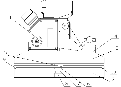
[0041] like figure 1 As shown, a stable optical azimuth automatic measuring device according to the embodiment of the present invention includes an optical azimuth 1 and a stable platform device. The optical azimuth 1 includes a circular base 4 and an instrument body 15 fixed on the circular base 4 . The stable platform equipment includes a servo adjustment platform and a support adapter structure 3 . The servo adjustment platform adopts a three-axis orthogonal frame 2 structure, and the three-axis orthogonal frame 2 is fixed on a support base 5 . The support fitting structure 3 of the present invention adopts the same installation bottom structure as the circular base 4, as long as it is used to support the servo adjustment platform and the optical azimuth 1, the servo adjustment platform and the optical azimuth 1 are integrated into one without gaps fit conversion.

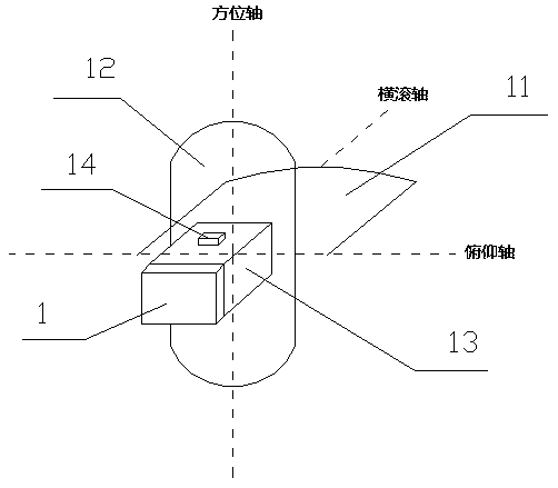
[0042] like figure 1 and 2 As shown, the three-axis orthogonal frame 2 is composed of the outer frame 11,...


PUM


Abstract

The invention discloses a stable optical orientation automatic measuring device and a measuring method thereof, and relates to the field of ship navigation measuring equipment. The stable optical orientation automatic measuring device according to the invention comprises an optical azimuth instrument, a servo adjusting platform and a supporting adaptive structural member, the servo adjusting platform is of a three-axis orthogonal frame structure, a three-axis orthogonal frame is fixed to the support type base, the supporting and adapting structural part is in sliding fit with the support typebase, and the supporting and adapting structural part adjusts the orientation of the optical azimuth instrument through a structure that a motor drives the servo adjusting platform. The supporting adaptive structural component further comprises a servo system, and the servo system is composed of a control unit, an orientation sensor, an information processing unit, a power supply unit and a display unit. According to the device, the continuous real-time effective observation of the optical azimuth instrument under severe sea conditions is realized, the full-automatic observation and accurate positioning of the target azimuth are realized, the uncertainty of manual operation is reduced, and the stability of the optical azimuth instrument and the accuracy of data are ensured.

Description

technical field [0001] The invention relates to the technical field of ship navigation measurement equipment, in particular to an optical orientation automatic measurement device and a measurement method thereof. Background technique [0002] The optical azimuth is referred to as the azimuth, which is used to accurately measure the target azimuth and ship angle in navigation. At present, all ships are equipped with optical azimuth as one of the means of observing the target azimuth of the ship. Due to its independence and high reliability, it is well received by ship pilots. However, when the traditional optical azimuth is used, due to the complexity of the sea situation, if the weather is bad and the waves are large, it cannot be observed at sea all-weather, which affects its normal use or reduces the accuracy of its observation. Therefore, it is necessary to provide an optical azimuth that can be observed in real time under harsh sea conditions, thereby improving the navi...

Claims


Application Information

Patent Timeline
Patent Type & Authority Applications(China)
IPC IPC(8): G01P13/02G01P1/00G01P1/04G01C21/16G01C21/18G01C1/00
CPCG01C1/00G01C21/165G01C21/18G01P1/00G01P1/04G01P13/02
Inventor 肖志伟江峦陈路
Owner HUNAN GUOTIAN ELECTRONICS TECH CO LTD
Why Eureka
Try Eureka