Method for controlling variable gain amplifier in infrared receiving chip

A technology of infrared receiving chip and gain amplifier, which is applied in the field of sensors, can solve the problems of high cost, excessive chip area, poor current stability, etc., and achieve the effect of low cost, stable change and stable change

Inactive Publication Date: 2020-06-23
无锡思泰迪半导体有限公司
View PDF0 Cites 0 Cited by
  • Summary
  • Abstract
  • Description
  • Claims
  • Application Information

AI Technical Summary

Problems solved by technology

[0007] In order to solve the existing problems of large chip area, high cost, and poor current stability, the present invention provides a method for controlling a variable gain amplifier in an external receiving chip, which can save a large amount of chip area, reduce costs, and improve current value stability

Method used


Image

  • Method for controlling variable gain amplifier in infrared receiving chip
  • Method for controlling variable gain amplifier in infrared receiving chip

Examples


Embodiment Construction

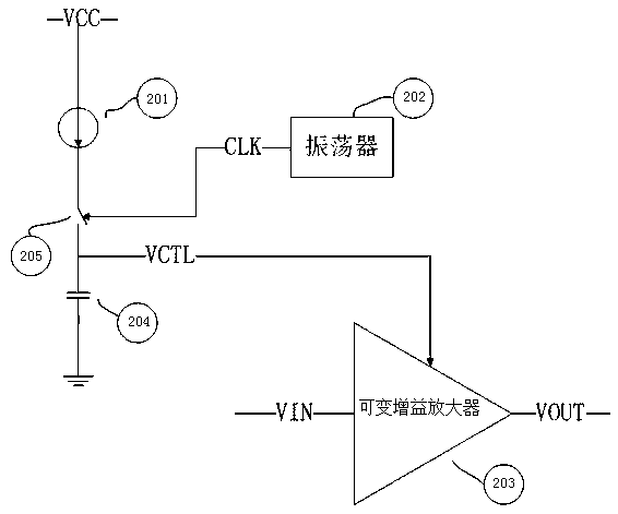
[0014] See figure 2 As shown, the fixed current source 201 is connected to the input terminal of the switch 205 , and the output terminal of the switch 205 is connected to the upper plate of the capacitor 204 . At the same time, the upper plate of the capacitor 204 is connected to the control voltage terminal of the variable gain amplifier 203 , and the output terminal of the oscillator 202 is connected to the control terminal of the switch 205 . Suppose the current value of the current source 201 is I, the capacitance value of the capacitor 204 is C, the period of the output signal of the oscillator 202 is T, the duty cycle is A, and the gain of the variable gain amplifier is V*g, where V is the gain Control voltage, g is the gain constant. Then the gain G of the variable gain amplifier 203 in a period T is expressed as:

[0015] G=V*g=[(I*T*A) / C]*g---------------------(1)

[0016] It can be seen from (1) that the rate of gain change of the variable gain amplifier can be ...


PUM


Abstract

The invention belongs to the field of sensors, the invention relates to a method for controlling a variable gain amplifier in an infrared receiving chip. The chip area can be greatly saved; reducing cost, improving stability of current values, the circuit comprises a current source, a capacitor and a variable gain method device, one end of the current source is connected with VCC, and the other end is connected with the input end of the switch. The output end of the switch is connected with the upper pole plate of the capacitor and the voltage control end of the variable gain method device; the control end of the switch is connected with the output end of the oscillator; the current value of the current source is set to be I; wherein the capacitance value of the capacitor is C, the periodof the output signal of the oscillator is T, the duty ratio is A, the gain of the variable gain amplifier is V * g, V is the gain control voltage, g is the gain constant, and the gain G of the variable gain amplifier in one period T is expressed as G = V * g = [(I * T * A)/C] * g; the gain change rate of the variable gain amplifier is controlled by adjusting the duty ratio of the output signal ofthe oscillator.

Description

technical field [0001] The invention belongs to the field of sensors, in particular to a method for controlling a variable gain amplifier in an infrared receiving chip. Background technique [0002] As one of the three major technologies of modern technology, sensing technology has been rapidly applied and developed in recent years. [0003] Infrared remote control is a technology that uses infrared as a signal carrier for long-distance control. It is an indispensable part of home appliances, toys and other products that require remote control. [0004] The infrared remote control receiving chip has the advantages of high reliability, low cost, low power consumption, strong anti-interference ability, etc., and can realize fast and reliable remote control. [0005] One of the most important indicators to measure the infrared remote control receiving chip is the receiving distance. To achieve a relatively long receiving distance, the slope of the gain change of the variable g...

Claims


Application Information

Patent Timeline
Patent Type & Authority Applications(China)
IPC IPC(8): H03G3/00
CPCH03G3/008
Inventor 马辉朱杰白月
Owner 无锡思泰迪半导体有限公司
Why Eureka
Try Eureka