Acoustic device and electronic apparatus

A technology for acoustic devices and electronic equipment, applied in the field of electronic equipment and acoustic devices, can solve the problems of negative effects on the sensitivity of the acoustic system, affecting the service life of the speaker unit, and damaging the acoustic performance of the speaker unit, so as to improve the low-frequency sensitivity, reduce the resonance frequency, Increase the effect of equivalent smoothness

Pending Publication Date: 2020-06-23
GOERTEK INC
View PDF1 Cites 0 Cited by
  • Summary
  • Abstract
  • Description
  • Claims
  • Application Information

AI Technical Summary

Problems solved by technology

However, there are problems in the above two methods. The first method of adding sound-absorbing materials to the cabinet needs to achieve good sealing and packaging of the sound-absorbing materials. Otherwise, if the sound-absorbing materials enter the speaker unit, it will damage the acoustic performance of the speaker unit and affect the speaker unit. The service life of the second type of passive radiator is adopted. Near the resonant frequency point fp, the passive radiator radiates strongly, and the sound unit almost stops. Therefore, the high-sensitivity design of the passive radiator can be used to realize the acoustic system in the frequency band near fp The local sensitivity is enhanced; but in the frequency band below fp, the phase of the passive radiator and the sound wave of the sounding unit are opposite, the sound waves cancel each other out, and the passive radiator has a negative effect on the sensitivity of the acoustic system
All in all, the passive radiator can only improve the sensitivity of the frequency band near the resonance point, but cannot improve the sensitivity of all low frequency bands.

Method used


Image

  • Acoustic device and electronic apparatus
  • Acoustic device and electronic apparatus
  • Acoustic device and electronic apparatus

Examples


Embodiment 1

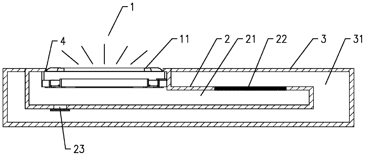
[0049] like image 3 As shown, an acoustic device includes a sounding unit 1, wherein, in this embodiment, the sounding unit 1 is a miniature sounding unit, more specifically, the sounding unit 1 is a miniature moving coil speaker. The sound unit 1 generally includes a housing and a vibration system and a magnetic circuit system fixed in the housing. The vibration system includes a vibrating diaphragm 11 fixed on the housing and a voice coil combined with the vibrating diaphragm 11. The magnetic circuit system is formed with The magnetic gap, the voice coil is set in the magnetic gap, and the voice coil reciprocates up and down in the magnetic field after being fed with alternating current, thereby driving the vibrating diaphragm 11 to vibrate and produce sound.

[0050] The acoustic device is provided with a sound outlet 4, and the sound waves on the front side of the vibrating membrane 11 are radiated to the outside through the sound outlet 4, and the sound waves on the back...

Embodiment 2

[0073] like Figure 7 As shown, the main difference between this embodiment and Embodiment 1 is that the flexible deformation part 22 in this embodiment is an independent installation part, and a through hole is provided on the isolation part (not marked), and the flexible deformation part 22 is installed on On the through hole, specifically, the flexible deformation portion 22 is fixedly connected to the first casing part around the through hole by bonding, welding or thermal fusion. This improved design is more convenient in the material selection of the flexible deformation part 22, and can achieve a more realistic combination with the first housing. At the same time, providing through holes on the first housing can simplify the realization of product technology.

Embodiment 3

[0075] The main difference between this embodiment and the above-mentioned embodiments is that the acoustic device in this embodiment is provided with a sound channel, and the sound channel corresponds to the design of the sound outlet 4, and the sound wave on the front side of the vibrating diaphragm 11 is radiated to the Sound outlet 4. This design is more in line with the design requirements of some terminal products, and will not occupy the space of the panel of the mobile phone, which is conducive to the design of the full screen, while avoiding the occlusion and interference of other components.

[0076] Specifically, such as Figure 8 As shown, the sound unit 1 is installed in the first casing 2, and the sound output channel is also arranged on the first casing 2. In other embodiments, it is also possible that the sound output channel is arranged on the second housing 3, and the sound output component is docked with the sound output channel; or, the sound output channe...


PUM


Abstract

The invention discloses an acoustic device, which comprises a sound production unit, the sound production unit comprises a vibrating diaphragm, the acoustic device is provided with a sound outlet, andsound waves at the front side of the vibrating diaphragm are radiated to the outside through the sound outlet; wherein a closed cavity is formed in the rear side of the vibrating diaphragm, the closed cavity is divided into a first closed cavity and a second closed cavity by a spacing part, the spacing part can be at least partially and flexibly deformed, the first closed cavity is adjacent to the vibrating diaphragm, the second closed cavity is far away from the vibrating diaphragm, and the volume of the second closed cavity is greater than that of the first closed cavity; the second closedcavity is used for closing sound waves generated by the flexible deformation part during deformation in the second closed cavity; at least one part of the shell of the electronic equipment used for installing the acoustic device is used for forming the first closed cavity and / or the second closed cavity. According to the acoustic device, the resonant frequency can be effectively reduced, and the low-frequency-band sensitivity of the product is greatly improved on the whole.

Description

technical field [0001] The present invention relates to the technical field of acoustics, and more specifically, to an acoustic device and electronic equipment installed with the acoustic device. Background technique [0002] Generally speaking, the acoustic system of the traditional structure (prior art 1) includes a closed box and a sounding unit arranged on the closed box, and a cavity is formed between the closed box and the sounding unit, because the cavity in the acoustic system Due to volume limitations, it is difficult for an acoustic system, especially a small acoustic system, to achieve a satisfactory reproduction of bass. Conventionally, in order to achieve satisfactory bass reproduction in an acoustic system, two methods are usually used. One is to place sound-absorbing materials (such as activated carbon, zeolite, etc.) in the box of the acoustic system for adsorption or desorption. The gas in the body has the effect of increasing the volume and reducing the lo...

Claims


Application Information

Patent Timeline
Patent Type & Authority Applications(China)
IPC IPC(8): H04R7/06H04R9/06H04R1/22
CPCH04R7/06H04R9/06H04R1/22H04R1/2834H04R1/2842H04R2499/11H04R1/30H04R1/2869H04R9/02H04R7/04
Inventor 刘春发徐同雁张成飞
Owner GOERTEK INC
Why Eureka
Try Eureka