Movable powder metallurgy forming equipment

A technology for powder metallurgy and molding equipment, which is applied in chemical instruments and methods, cleaning methods and utensils, cleaning methods using tools, etc., and can solve the problems of inconvenient movement of molding equipment and difficulty in taking out finished products.

Inactive Publication Date: 2020-06-26
NINGBO QUNXING POWDER METALLURGY
View PDF7 Cites 4 Cited by
  • Summary
  • Abstract
  • Description
  • Claims
  • Application Information

AI Technical Summary

Problems solved by technology

[0003] After the existing powder metallurgy molding equipment is processed, it is difficult to take out the finished product, and the molding equipment is inconvenient to move

Method used


Image

  • Movable powder metallurgy forming equipment
  • Movable powder metallurgy forming equipment
  • Movable powder metallurgy forming equipment

Examples


Embodiment 1

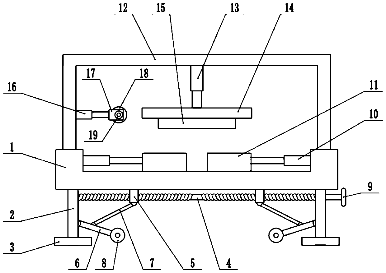
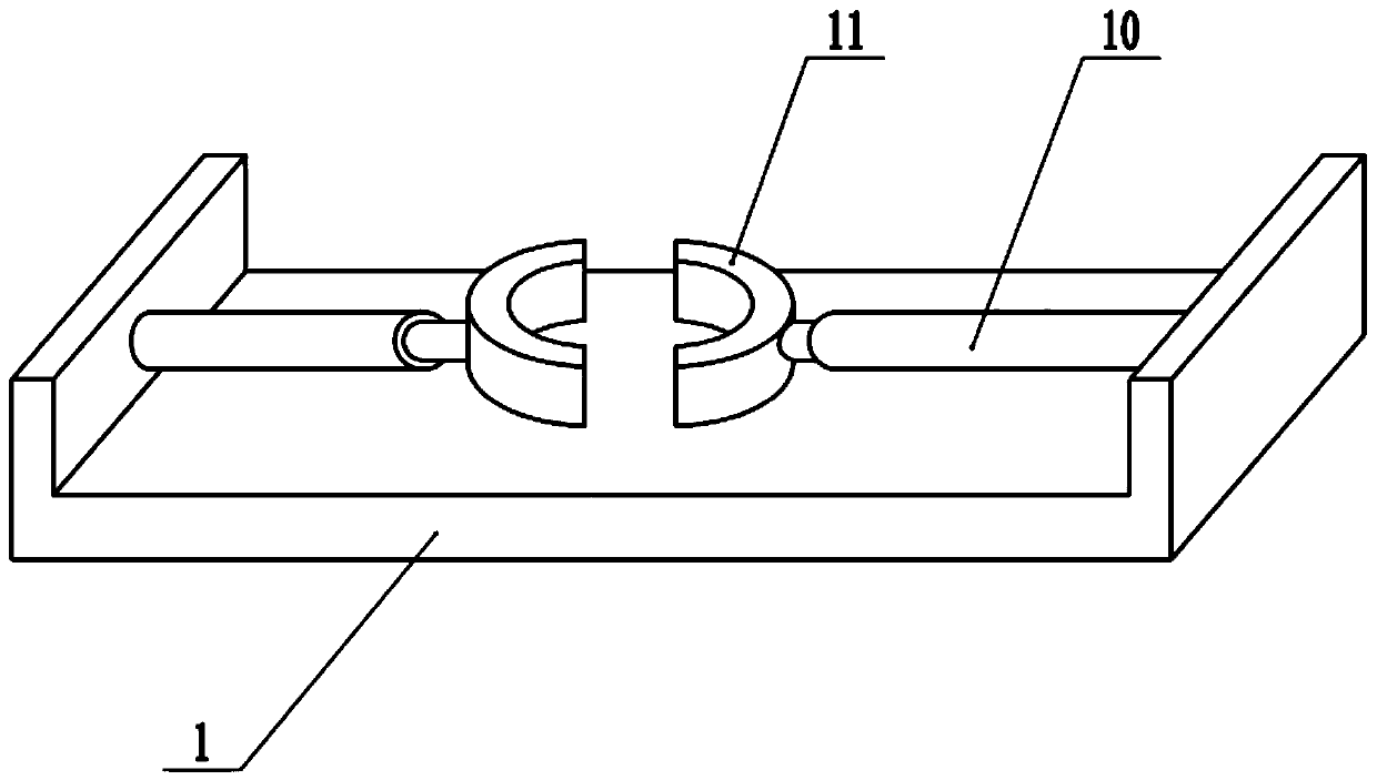
[0022] see Figure 1-3 , in an embodiment of the present invention, a mobile powder metallurgy molding equipment, including a workbench 1, a support plate 2, a fixed frame 12, a lifting plate 14 and an upper mold 15, the bottom of the workbench 1 is fixedly connected with a support plate 2, supporting There are two boards 2, which are symmetrically arranged left and right. The bottom of the support plate 2 is fixedly connected with a base plate 3 to keep the device stable. The bottom of the workbench 1 is provided with a two-way screw rod 4, and the two ends of the two-way screw rod 4 are connected to the support plate respectively. 2 rotating connection, the right end of the two-way screw rod 4 is equipped with a turntable 9, the two-way screw rod 4 is covered with a slider 5, there are two sliders 5, left and right symmetrically arranged, the lower surface of the slider 5 is hinged with a connecting rod 7, The side wall of the support plate 2 is hinged with a movable rod 6, ...

Embodiment 2

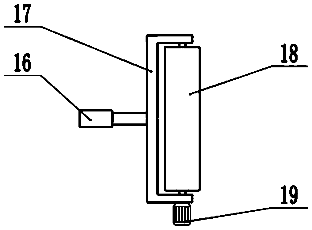
[0024] On the basis of Embodiment 1, a cleaning mechanism is also installed on the side wall of the fixed mount 12, and the cleaning mechanism includes a third telescopic mechanism 16, a mounting frame 17, a cleaning roller 18 and a cleaning motor 19, and the side wall of the fixed mount 12 is fixedly connected with The 3rd expansion mechanism 16, the 3rd expansion mechanism 16 is electro-hydraulic telescopic cylinder, the extension end of the 3rd expansion mechanism 16 is fixedly connected with mounting frame 17, and the interior rotation of mounting frame 17 is connected with cleaning roller 18, and the surface of cleaning roller 18 Bristles are distributed, and the outer side wall of the mounting frame 17 is fixedly connected with a cleaning motor 19. The shaft extension end of the cleaning motor 19 is connected with the end of the cleaning roller 18, and the cleaning motor 19 is started to drive the cleaning roller 18 to rotate. When the lower surface of the mold 15 is clea...


PUM


Abstract

The invention relates to the field of machining equipment, in particular to movable powder metallurgy forming equipment. The movable powder metallurgy forming equipment comprises a workbench, a supporting plate, a fixing frame, a lifting plate and an upper die, wherein a bidirectional lead screw is arranged below the workbench, the bidirectional lead screw is sleeved with a sliding block, a connecting rod is hinged to the lower surface of the sliding block, a movable rod is hinged to the side wall of the supporting plate, lower dies are installed on the workbench, the fixing frame is fixedly connected to the workbench, a second telescopic mechanism is fixedly connected to the top of the fixing frame, the lifting plate is fixedly connected to the lower end of the second telescopic mechanism, the upper die is fixedly connected to the lower surface of the lifting plate, and a cleaning mechanism is further installed on the side wall of the fixing frame. The two lower dies are separated through the first telescopic mechanism, a pressed and formed finished product can be conveniently taken out, the lower surface of the upper die can be cleaned by using the cleaning mechanism, raw material adhering to the lower surface of the upper die is removed, the trouble of manual cleaning is omitted, and the movable powder metallurgy forming equipment can be conveniently pushed to move through arrangement of liftable universal wheels.

Description

technical field [0001] The invention relates to the field of mechanical processing equipment, more specifically, a mobile powder metallurgy forming equipment. Background technique [0002] Powder metallurgy is a process technology for producing metal powder or using metal powder (or a mixture of metal powder and non-metal powder) as raw material, forming and sintering to manufacture metal materials, composite materials and various types of products. [0003] The existing powder metallurgy molding equipment is difficult to take out the finished product after processing and molding, and the molding equipment is inconvenient to move. Contents of the invention [0004] The purpose of the present invention is to provide a mobile powder metallurgy molding equipment to solve the problems raised in the above background technology. [0005] To achieve the above object, the present invention provides the following technical solutions: [0006] A mobile powder metallurgy molding eq...

Claims


Application Information

Patent Timeline
Patent Type & Authority Applications(China)
IPC IPC(8): B22F3/03B22F3/00B08B1/04
CPCB22F3/03B22F3/005B22F3/003B08B1/04B08B1/002
Inventor 潘成群
Owner NINGBO QUNXING POWDER METALLURGY
Why Eureka
Try Eureka