
Plate positioning device for laser cutting

A laser cutting and positioning device technology, applied in auxiliary devices, laser welding equipment, welding/cutting auxiliary equipment, etc., can solve the problems affecting the production efficiency and progress of enterprises, large workload, poor alignment effect, etc., to improve cutting Efficiency and effect of cutting progress

Active Publication Date: 2020-06-26
GUANGDONG SAMPU GARAGE CO LTD +1
View PDF8 Cites 3 Cited by
  • Summary
  • Abstract
  • Description
  • Claims
  • Application Information

AI Technical Summary

Problems solved by technology

[0002] Laser cutting is an emerging cutting technology, which uses a high-power-density laser beam to irradiate the material to be cut, so that the material is quickly heated to the vaporization temperature, evaporates to form holes, and continuously forms narrow slits with the movement of the beam relative to the material. , so that the cutting of the material can be completed. The laser cutting process will generate a lot of heat. Before the laser cutting of the plate, it is manually loaded. Whether the plate is placed in the correct position requires manual alignment, and the workload is large. The alignment effect is poor, and laser cutting equipment is required to find the edge of the cutting plate during cutting, which seriously affects the production efficiency and progress of the enterprise

Method used


Image

  • Plate positioning device for laser cutting
  • Plate positioning device for laser cutting
  • Plate positioning device for laser cutting

Examples


Embodiment

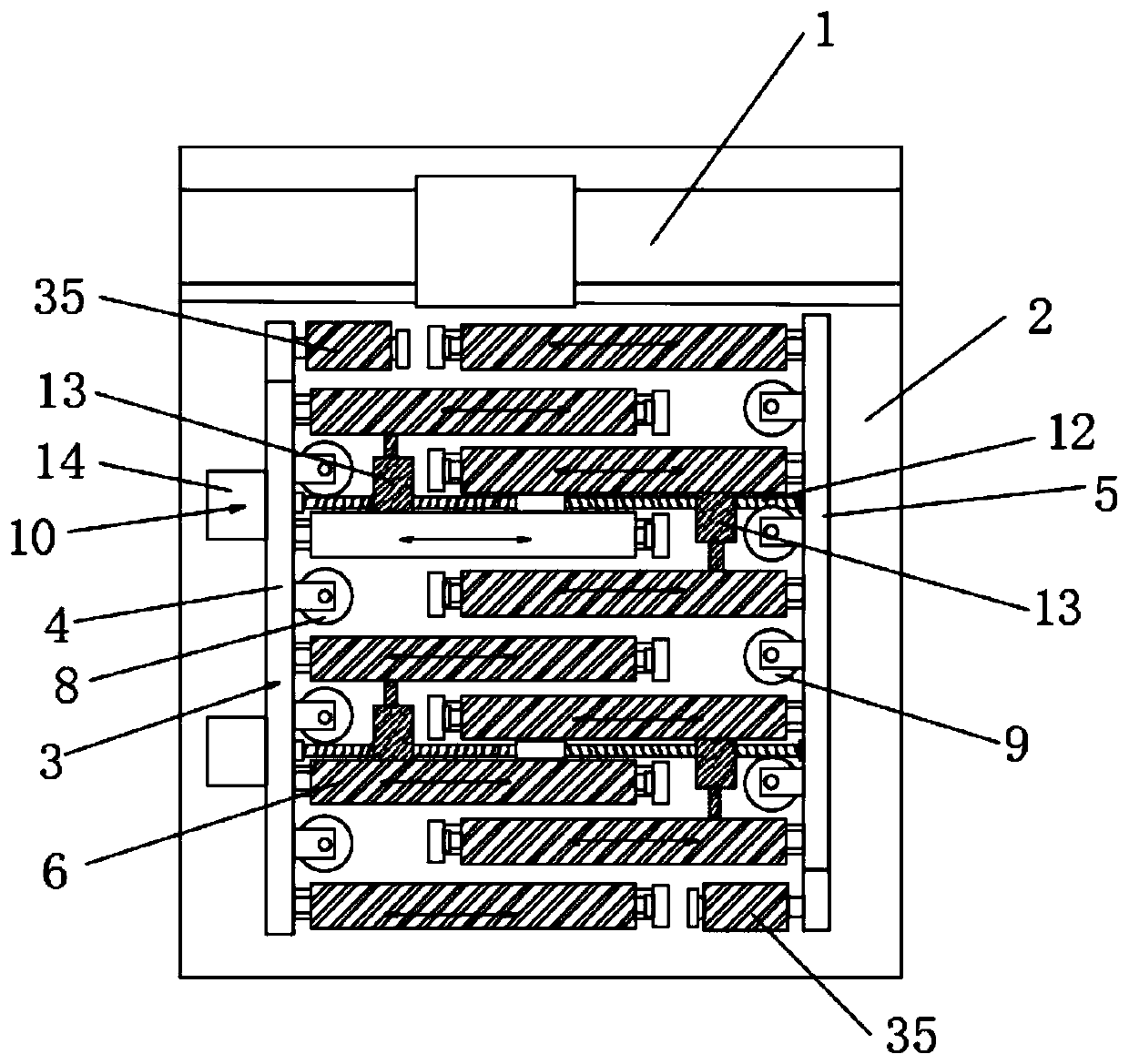
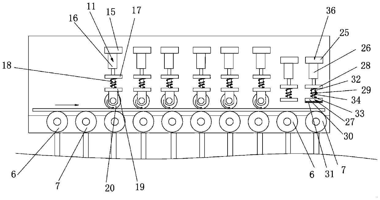
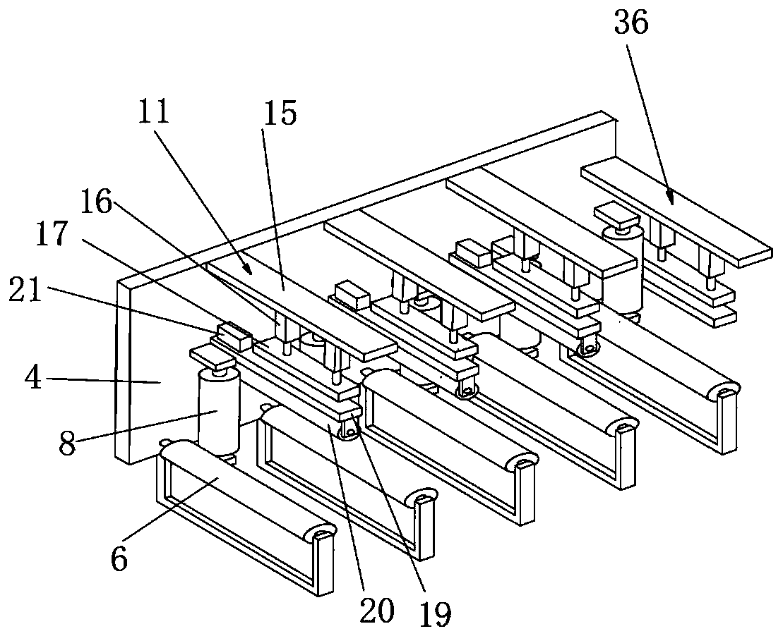
[0025] Embodiment: a kind of plate positioning device for laser cutting, such as Figure 1-6As shown, it includes a base frame 2 docked with the laser cutting device 1, and the base frame 2 is provided with a plate centering positioning frame 3, and the plate centering positioning frame 3 includes a first moving frame 4 and a second moving frame oppositely arranged 5. The first moving frame 4 is provided with a plurality of first rotating rollers 6, and the second moving frame 5 is provided with a plurality of second rotating rollers 7 set at the same height as the first rotating rollers 6, adjacent to the first rotating rollers Insertion gaps are respectively provided between a turning roller 6 and between adjacent second turning rollers 7, and the first turning roller 6 and the second turning roller 7 are arranged in a staggered manner and form a conveying roller table; the first moving The inner side of the frame 4 is provided with a plurality of vertically arranged first s...


PUM


Abstract

The invention discloses a plate positioning device for laser cutting. The plate positioning device comprises a base frame in butt joint with a laser cutting device, wherein a plate centering positioning frame is arranged on the base frame and comprises a first moving frame and a second moving frame which are oppositely arranged; a plurality of first rotating rollers are arranged on the first moving frame; a plurality of second rotating rollers which are as high as the first rotating rollers are arranged on the second moving frame; inserting gaps are formed between the adjacent first rotating rollers and between the adjacent second rotating rollers correspondingly; the first rotating rollers and the second rotating rollers are arranged in a staggered mode and form a conveying roller way; and plate positioning conveying mechanisms are arranged on the first moving frame and the second moving frame correspondingly. According to the plate positioning device, plates are centered, positionedand conveyed, the to-be-cut plates are fed into the laser cutting device at a fixed placement position, thus precise positioning feeding of the laser cutting device is achieved, and the cutting efficiency and the cutting progress are effectively improved.

Description

technical field [0001] The invention relates to the technical field of laser cutting and manufacturing, in particular to a plate positioning device for laser cutting. Background technique [0002] Laser cutting is an emerging cutting technology, which uses a high-power-density laser beam to irradiate the material to be cut, so that the material is quickly heated to the vaporization temperature, evaporates to form holes, and continuously forms narrow slits with the movement of the beam relative to the material. , so that the cutting of the material can be completed. The laser cutting process will generate a lot of heat. Before the laser cutting of the plate, it is manually loaded. Whether the plate is placed in the correct position requires manual alignment, and the workload is large. The alignment effect is poor, and laser cutting equipment is required to find the edge of the cut sheet during cutting, which seriously affects the production efficiency and progress of the ente...

Claims


Application Information

Patent Timeline
Patent Type & Authority Applications(China)
IPC IPC(8): B23K26/70B23K37/04B23K26/38
CPCB23K26/702B23K37/0408B23K26/38
Inventor 廖志林礼区温文文金江成
Owner GUANGDONG SAMPU GARAGE CO LTD
Learn More