Thermal printer

A technology of thermal printers and thermal sheets, applied in printing devices, printing, etc., can solve problems such as thermal melting of rubber rollers, damage of thermal sheets, damage of rubber rollers, etc., and achieve the effect of protecting rubber rollers

Active Publication Date: 2020-06-26
深圳市易联达商用设备有限公司
View PDF6 Cites 1 Cited by
  • Summary
  • Abstract
  • Description
  • Claims
  • Application Information

AI Technical Summary

Problems solved by technology

During the printing process, the temperature of the thermal sheet can reach 200°C. When the thermal paper in the paper bin is used up, there is no paper between the thermal sheet and the rubber roller, and the thermal sheet can easily separate the thermal sheet from the rubber roller. The surface melts, which damages the rubber roller, and at the same time, the thermal film is also contaminated with the melted colloid of the rubber roller, which damages the thermal film. For this reason, the existing thermal printer is equipped with a system for detecting the state of the printer. When there is no paper in the printing path, the display screen of the thermal printer will indicate that there is no paper
[0004] The above-mentioned existing technical solutions have the following defects: Although the thermal printer will display the paperless state, the prompt is not obvious enough, causing people to forget to replace the thermal paper, so that the thermal sheet will still generate a lot of heat and the rubber roller will be heated. melting, so it is necessary to improve the above-mentioned prior art

Method used


Image

  • Thermal printer
  • Thermal printer
  • Thermal printer

Examples


Embodiment Construction

[0047] The present invention will be further described in detail below in conjunction with the drawings.

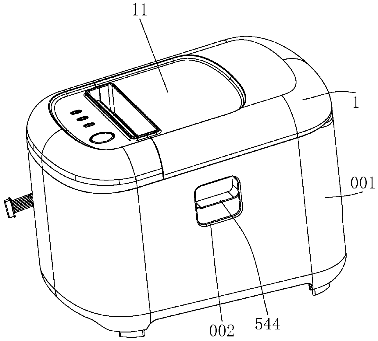
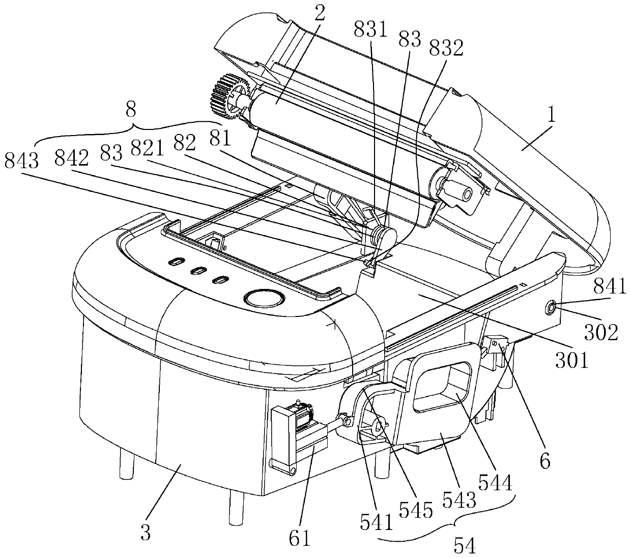
[0048] Reference figure 1 , figure 2 , Is a thermal printer provided by the present invention, comprising an upper cover 1, an outer shell 001 and an inner shell 3, wherein the inner shell 3 is located inside the outer shell 001, and the rotating end of the upper cover 1 is rotatably connected with the inner shell 3. Further, The upper cover 1 and the inner shell 3 are connected by a flip structure 8, and the free end of the upper cover 1 can be turned from a position close to the inner shell 3 to a position where the free end is far away from the inner shell 3.

[0049] Specifically, the aforementioned flip structure 8 includes a hinged leg 81, a supporting plate 82, a torsion spring 83 and a connecting rod 84. The hinged legs 81 are integrally connected with the upper cover 1, the hinged legs 81 are arranged on both sides of the free end of the upper cover 1, and the two hi...


PUM


Abstract

The invention relates to the technical field of thermal printers, in particular to a thermal printer. The thermal printer comprises an upper cover and an inner shell, wherein the rotating end of the upper cover is rotationally connected with the inner shell, the free end of the upper cover is rotationally connected with a rubber roller, a thermal sensitive piece is arranged in the inner shell, andwhen the free end of the upper cover is closed with the inner shell, the rubber roller abuts against the side face of the thermal sensitive piece; the thermal printer further comprises a paper bin box used for containing thermal sensitive paper, a containing cavity used for installing the paper bin box, a cover opening device used for separating the free end of the upper cover from the inner shell when it is detected that no thermal sensitive paper exists in the printing channel and a cover overturning structure used for overturning the upper cover till the free end is away from the inner shell and connected between the rotating end of the upper cover and the inner shell; an opening of the paper bin box faces the upper cover and is detachably fixed to the upper cover; and when the upper cover is closed, the paper bin box is located in the containing cavity. According to the thermal printer, the paper bin box can be popped up in time after the thermal sensitive paper is printed, so that the rubber roller is separated from the thermal sensitive piece, and the thermal sensitive piece and the rubber roller are protected.

Description

Technical field [0001] The invention relates to the technical field of thermal printers, in particular to a thermal printer. Background technique [0002] Invoice printers are also called thermal printers. Thermal printers are mainly used to print transaction receipts, bills, labels, etc., so they are widely used in the retail industry, catering industry, logistics industry and other fields. Due to the particularity of these industries, hot The frequency of use of sensitive printers far exceeds that of conventional commercial printers. At present, a thermal printer is equipped with a semiconductor heating element on the print head. After the print head is heated and contacts the thermal paper, it can print the required patterns. The principle is similar to that of a thermal fax machine. The appearance of the image is generated by heating the thermal paper and generating a chemical reaction on the surface of the thermal paper. This thermal printer chemical reaction is carried ou...

Claims


Application Information

Patent Timeline
Patent Type & Authority Applications(China)
IPC IPC(8): B41J2/325B41J11/00B41J29/12B41J29/38B41J29/18B41J29/46
CPCB41J2/325B41J11/0075B41J29/12B41J29/18B41J29/38B41J29/46
Inventor 陈海汪发刘武
Owner 深圳市易联达商用设备有限公司
Why Eureka
Try Eureka