An automatic stop device for equipment trains in fully mechanized mining transportation lanes in coal mines
A technology for equipment trains and transportation lanes, which is applied in the direction of transportation and packaging, railway braking systems, railway car body parts, etc., and can solve the problems of manual placement of vehicle arresters, affecting the working efficiency of mobile equipment trains, and consuming time and labor. Achieve the effect of saving time and labor, improving work efficiency and realizing automation
- Summary
- Abstract
- Description
- Claims
- Application Information
AI Technical Summary
Problems solved by technology
Method used
Image
Examples
Embodiment 1
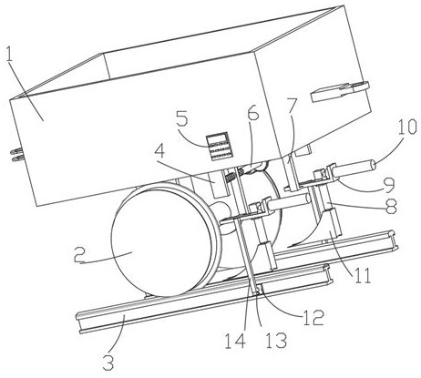
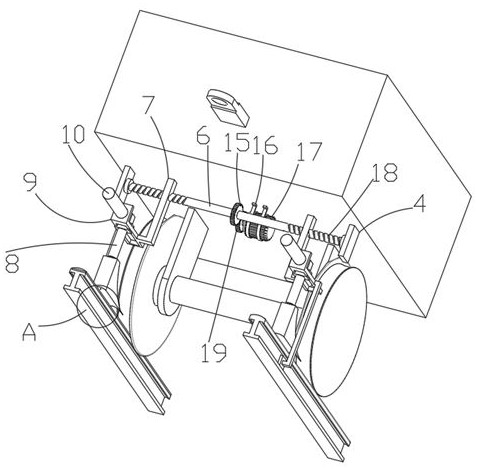
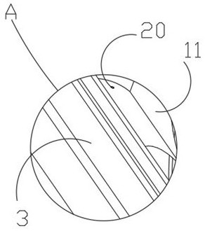
[0033] Such as Figure 1-5Shown is an automatic train stop device for fully mechanized mining transportation lane equipment, including a train box 1, train rollers 2 and rails 3, the train box 1 is connected to the train rollers 2 through the rotation of the outriggers, and the train rollers 2 are movably connected to the rails 3 The bottom of the right end of the train case 1 is fixedly connected with a straight plate 4 symmetrically front and back, the inner wall of the straight plate 4 is fixedly connected with a rotating rod 6, and the rotating rod 6 is symmetrically provided with thread grooves 18, and the bottom of the train case 1 is provided with a driving structure for driving the rotating rod 6 to rotate. The driving structure includes a driving motor 17, a driving ring gear 19 and a driven ring gear 15. The driving motor 17 is fixedly connected with a driving ring gear 19 through a fixedly connected reducer, and the driving ring gear 19 is engaged with the driven rin...
Embodiment 2
[0035] Such as Figure 1-5 As shown, a fully-mechanized mining transportation lane equipment train automatic stop device, including a train box 1, a train roller 2 and a rail 3, the train box 1 is connected to the train roller 2 through the rotation of the legs, and the train roller 2 is movably connected to the rail 3 The bottom of the right end of the train case 1 is fixedly connected with a straight plate 4 symmetrically front and back, the inner wall of the straight plate 4 is fixedly connected with a rotating rod 6, and the rotating rod 6 is symmetrically provided with thread grooves 18, and the bottom of the train case 1 is provided with a driving structure for driving the rotating rod 6 to rotate. The rotating rod 6 is connected with an L-shaped slide plate 7 through threaded grooves 18. The outer end of the L-shaped slide plate 7 is fixedly connected with an L-shaped mounting plate 9. The upright position of the L-shaped mounting plate 9 is fixedly connected with a seco...
Embodiment 3
[0037] Such as Figure 1-5 As shown, a fully-mechanized mining transportation lane equipment train automatic stop device, including a train box 1, a train roller 2 and a rail 3, the train box 1 is connected to the train roller 2 through the rotation of the legs, and the train roller 2 is movably connected to the rail 3 The bottom of the right end of the train case 1 is fixedly connected with a straight plate 4 symmetrically front and back, the inner wall of the straight plate 4 is fixedly connected with a rotating rod 6, and the rotating rod 6 is symmetrically provided with thread grooves 18, and the bottom of the train case 1 is provided with a driving structure for driving the rotating rod 6 to rotate. The rotating rod 6 is connected with an L-shaped slide plate 7 through threaded grooves 18. The outer end of the L-shaped slide plate 7 is fixedly connected with an L-shaped mounting plate 9. The upright position of the L-shaped mounting plate 9 is fixedly connected with a seco...
PUM
 Abstract
Description
Claims
Application Information
 - R&D
- Intellectual Property
- Life Sciences
- Materials
- Tech Scout
- Unparalleled Data Quality
- Higher Quality Content
- 60% Fewer Hallucinations
Browse by: Latest US Patents, China's latest patents, Technical Efficacy Thesaurus, Application Domain, Technology Topic, Popular Technical Reports.
© 2025 PatSnap. All rights reserved.Legal|Privacy policy|Modern Slavery Act Transparency Statement|Sitemap|About US| Contact US: help@patsnap.com


