Cement silo clearing device and silo clearing method

A cement and warehouse cleaning technology, applied in the field of machinery, can solve the problems of low efficiency, high physical harm to workers, high risk to life, etc., to achieve high work efficiency, avoid the danger of suspended work, and take up less space.

Pending Publication Date: 2020-06-26
宜宾钢猫科技有限公司
View PDF0 Cites 0 Cited by
  • Summary
  • Abstract
  • Description
  • Claims
  • Application Information

AI Technical Summary

Problems solved by technology

[0004] The object of the present invention is to provide a cement warehouse cleaning device and method, which are used to solve the shortcomings of low efficiency of manual cleaning in the existing reservoir wall cleaning operations, and high hazards to workers' health and high life expectancy. dangerous question

Method used


Image

  • Cement silo clearing device and silo clearing method
  • Cement silo clearing device and silo clearing method
  • Cement silo clearing device and silo clearing method

Examples


Embodiment 1

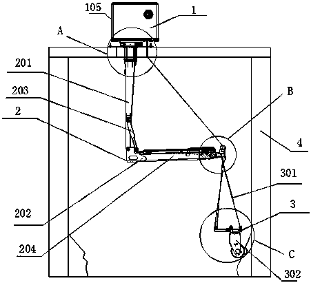
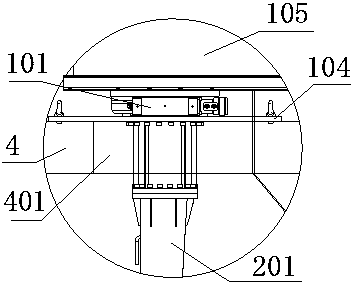
[0037] Such as Figure 1-5 As shown, the cement warehouse cleaning device includes a top fixing mechanism 1, a mechanical arm 2 connected to the lower end of the top fixing mechanism 1, and a power mechanism 3 installed on the mechanical arm 2;

[0038] Described mechanical arm 2 comprises mechanical revolving arm 201 and mechanical telescoping arm 202, is rotatably connected between one end of mechanical revolving arm 202 and top fixing mechanism 1, and mechanical revolving arm 202 is driven by the rotating motor that is installed on the top fixing mechanism 1 101 drives the rotation, the other end of the mechanical revolving arm 201 is hinged with the mechanical telescopic arm 202, and the rotation between the mechanical telescopic arm 202 and the mechanical revolving arm 201 is controlled by the folding device 203 installed on the mechanical revolving arm 201;

[0039] The power mechanism 3 includes a lifting mechanism 301 and a power head 302. The lifting mechanism 301 is ...

Embodiment 2

[0055] Such as Figure 6 , Figure 7 As shown, in this embodiment, on the basis of Embodiment 1, the rope 305 extends to the winch 102 through the hollow channel 205 of the mechanical slewing arm 201. If it enters the installation box 105 directly from the opening on the top of the cement silo, The rope 305 will be in contact with the wall at the hole, and the requirements for the hole are very high. It needs to be polished to avoid serious wear of the rope 305. Now it directly enters the hollow to 205, and then there will be friction between the rope and the mechanical rotating arm 201. The embodiment is that an inlet is set on the side wall of the mechanical swing arm 201, and an outlet is set at the upper end of the mechanical swing arm 201, so we process it into a smooth edge at the entrance, so that the wear of the rope 305 is very little.

Embodiment 3

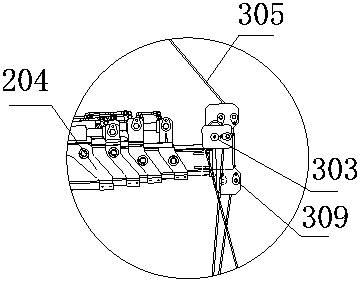
[0057] Such as Figure 8 , Figure 9 As shown, in this embodiment, on the basis of Embodiment 2, two pulleys clamp the rope 305 at the entrance of the lower end of the hollow passage 205 to facilitate the movement of the rope 305. In this embodiment, two pulleys clamp the rope 305 directly. 305, when the rope 305 is in motion, it will not rub against the edge of the entrance, which protects the rope 305.


PUM


Abstract

The invention discloses a cement silo clearing device and a silo clearing method. The device comprises a top fixing mechanism, a mechanical arm connected to the lower end of the top fixing mechanism and a power mechanism installed on the mechanical arm. According to the device, a hole is directly formed in the top of a cement silo, and a power head is placed deeply in the cement silo; transversely, movement is controlled through a telescoping mechanism, and the movement range can reach 11m; longitudinally, movement is controlled through a lifting mechanism, and the movement range can reach 50m, so that all positions in the cement silo are cleared; since control equipment is located at the top of the cement silo, an operator can perform silo clearing just at the top of the silo, the situation that a worker enters the silo is avoided, no hurt is brought to the health of the worker, and the risk in suspending operation is avoided; and moreover, all-mechanical operation is realized, so that working efficiency is high.

Description

technical field [0001] The invention relates to the field of mechanical technology, in particular to a cement warehouse cleaning device and a warehouse cleaning method. Background technique [0002] At present, the traditional manual warehouse clearing method uses the warehouse personnel to bind the body with a safety rope and hang it on the cement warehouse wall with a height of tens of meters to carry out the warehouse clearing operation. Clearing the warehouse, this method of clearing the warehouse is extremely inefficient and time-consuming and labor-intensive. Although the equipment cost is low, the labor cost is particularly high, and the overall cost is also very high. Of course, mechanical equipment is also used, such as operation Workers hold electric drills, which improves efficiency, but workers are still working in the long-term suspended high-altitude operation, and they are always facing various life-threatening dangers such as falling objects, high ash burial,...

Claims


Application Information

Patent Timeline
Patent Type & Authority Applications(China)
IPC IPC(8): B65G69/02
CPCB65G69/02B65G2201/04
Inventor 熊斌张洪李勇军谭军
Owner 宜宾钢猫科技有限公司
Why Eureka
Try Eureka