
Sand box type jacking structure

A sand box and jacking technology, which is applied in building construction, on-site preparation of building components, formwork/formwork/working frame, etc., can solve the problem that the height of high formwork formwork cannot meet the design requirements, steel structure support frame The height cannot be adjusted, the bearing capacity of the bolt-type jacking is not large, etc., to achieve the effect of simple production, accurate and convenient use, and strong bearing capacity

Inactive Publication Date: 2020-06-26
MCC5 GROUP CORP SHANGHAI
View PDF6 Cites 0 Cited by
  • Summary
  • Abstract
  • Description
  • Claims
  • Application Information

AI Technical Summary

Problems solved by technology

[0002] In the field of building high formwork construction, various types of support frames are installed under the formwork, and the top of the support frame uses adjustable bolt-type jacks to support the height of the high formwork bottom plate. The diameter of the bolts used for these jacks is generally not greater than 48mm , the bearing capacity of the bolt-type jacking is not large; when the high-support formwork needs to cross roads, rivers, etc., the span between the high-form support frames increases, and the load acting on the support frames is also large. The formwork support frame needs to use steel columns to replace the general scaffolding support frame. The adjustable bolt type jacking is not suitable for this occasion due to its small bearing capacity; Settlement pressure test to eliminate the settlement of the formwork and the deformation of the bracket gap. At this time, the height of the formwork will be reduced, and the height of the traditional steel structure support frame cannot be adjusted, resulting in the height of the high-support formwork after the pressure test. Affect the quality of subsequent concrete pouring; these are undesirable for those skilled in the art

Method used


Image

  • Sand box type jacking structure
  • Sand box type jacking structure
  • Sand box type jacking structure

Examples


Embodiment Construction

[0024] The structure of the present invention will be further described below in conjunction with the accompanying drawings and specific embodiments, but it is not intended as a limitation of the present invention.

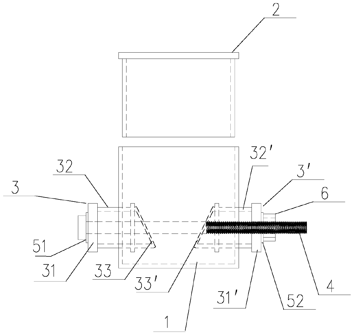
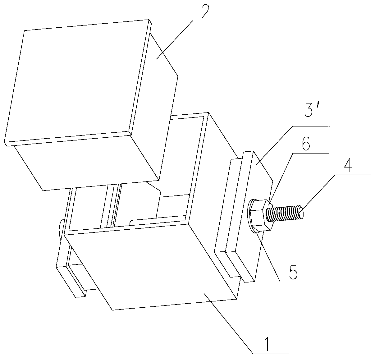
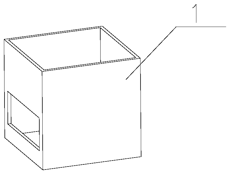
[0025] Such as Figure 1~5 As shown, the present invention discloses a sandbox-type jacking structure, which is set between the high-support formwork support frame and the high-support formwork formwork to adjust the elevation of the high-formwork formwork; specifically, the sand The box-type jacking structure includes: the lower sand box 1, the upper sand box 2, the first movable sand box 3, the second movable sand box 3', the rotating bolt 4 and the nut 6; the lower sand box 1 has an opening at the top, and the upper sand box 2 The bottom is open, and the upper sand box 2 is set in the lower sand box 1; both sides of the lower sand box 1 are oppositely opened with square holes to serve as passages for the first movable sand box 3 and the second movable sand box ...


PUM


Abstract

The invention relates to the technical field of building construction, in particular to a sand box type jacking structure. An upper sand box with the bottom being open is arranged in a lower sand boxwith the top being open. The two sides of the lower sand box are provided with movable moving sand boxes correspondingly. The interval between the two movable moving sand boxes is adjusted through rotating bolts and nuts, so that the size of the inner space of the lower sand box is changed, sand in the lower sand box pushes the upper sand box to move up and down, and then the elevation of a bottomformwork of a high formwork can be accurately adjusted; the sand box type jacking structure has the advantages of being large in contact area with the bottom formwork of the high formwork and a supporting frame of the high formwork, high in bearing capacity, easy to manufacture, accurate and convenient to use, safe, reliable, capable of being repeatedly used and good in economical efficiency; andthe sand box type jacking structure can be widely used for construction operation of large-span high-formwork supporting frame needing height adjustment at any time.

Description

technical field [0001] The invention relates to the technical field of building construction, in particular to a sand box type jacking structure. Background technique [0002] In the field of building high formwork construction, various types of support frames are installed under the formwork, and the top of the support frame uses adjustable bolt-type jacks to support the height of the high formwork bottom plate. The diameter of the bolts used for these jacks is generally not greater than 48mm , the bearing capacity of the bolt-type jacking is not large; when the high-support formwork needs to cross roads, rivers, etc., the span between the high-form support frames increases, and the load acting on the support frames is also large. The formwork support frame needs to use steel columns to replace the general scaffolding support frame. The adjustable bolt type jacking is not suitable for this occasion due to its small bearing capacity; Settlement pressure test to eliminate th...

Claims


Application Information

Patent Timeline
Patent Type & Authority Applications(China)
IPC IPC(8): E04G11/48E04G11/36
CPCE04G11/36E04G11/483
Inventor 蔡静
Owner MCC5 GROUP CORP SHANGHAI
Learn More