Lens optical axis offset method convenient for secondary adjustment

A technology of optical axis offset and optical axis, applied in optics, optical components, installation, etc., can solve the problems of complex optical adjustment, large space occupation, and unfavorable secondary adjustment of optical axis, etc., to simplify the adjustment process, The effect of convenient secondary operation and small volume

Inactive Publication Date: 2020-06-26
北京长峰科威光电技术有限公司
View PDF0 Cites 0 Cited by
  • Summary
  • Abstract
  • Description
  • Claims
  • Application Information

AI Technical Summary

Problems solved by technology

This offset method takes up a lot of space, and the optical adjustment is complicated, which is not conducive to the secondary adjustment of the optical axis

Method used


Image

  • Lens optical axis offset method convenient for secondary adjustment
  • Lens optical axis offset method convenient for secondary adjustment
  • Lens optical axis offset method convenient for secondary adjustment

Examples


Embodiment Construction

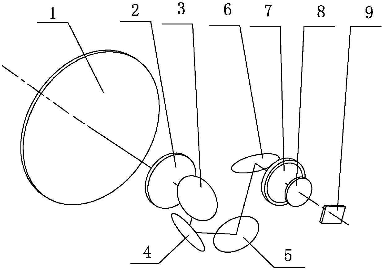
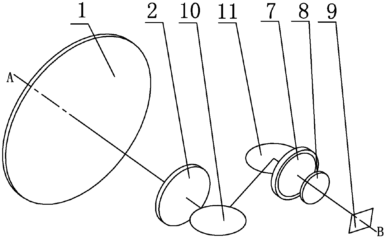
[0017] like image 3 , Figure 4 As shown, the present invention adopts a front mirror group 1, a relay image transfer front group 2, a first reflector 10, a second reflector 11, a relay image transfer rear group 7, a detector protection window 8, and a detector sensing surface 9 And the inclined pad 12 forms the optical axis offset system; the front mirror group 1, the relay image transfer front group 2, the first reflector 10, the second reflector 11, the relay image transfer rear group 7, the detector protection The window 8 and the detector sensing surface 9 are arranged in the lens barrel, and the inclined pad 12 is arranged outside the lens barrel;

[0018] The front mirror group 1 and the relay relay front group 2 are parallel to each other and the optical axes coincide; the relay relay rear group 7, the detector protection window 8 and the detector sensing surface 9 are parallel to each other and the optical axes coincide;

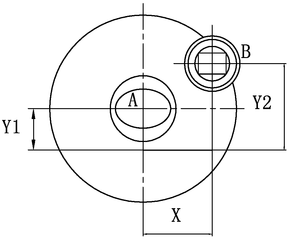
[0019] It is stipulated that the optical a...


PUM


Abstract

The invention provides a lens optical axis offset method convenient for secondary adjustment. A front lens group, a relay image rotation front group, a first reflector, a second reflector, a relay image rotation rear group, a detector protection window, a detector induction surface and an inclined cushion block form an optical axis offset system; an included angle of 45 degrees is formed between the first reflecting mirror and the relay image inversion front group, and the second reflecting mirror is perpendicular to the first reflecting mirror; the long side direction of the detector sensingsurface is defined as the x axis of the coordinate system, and a certain included angle is formed between the connecting line of the front lens group center and the detector sensing surface center andthe x axis; the inclined cushion block is of a triangular prism structure, the edge is arranged along the length direction of the lens cone, and the upper edge is parallel to the connecting line of the center of the front lens group and the center of the detector sensing surface; by adjusting the inclination angle of the side, close to the lens cone, of the inclined cushion block, deviation of the optical axis can be achieved.

Description

technical field [0001] The invention belongs to the technical field of cooling infrared thermal imaging, and in particular relates to a small-volume, low-cost and easy-to-adjust spatial optical axis offset method. Background technique [0002] In the design process of the cooled infrared thermal imaging lens, in order to ensure 100% cold aperture effect, a relay transfer system will be used to match the optical system aperture with the built-in aperture of the cooled infrared detector. Due to the introduction of the relay image transfer system and the large size of the cooled infrared detector, in order to reduce the space occupied by the optical system or adapt to different outer envelopes, designers usually use the method of shifting the optical axis. [0003] Traditional optical axis offset methods such as figure 1 As shown, it includes the front mirror group 1, the relay image transfer front group 2, the mirror 1 3, the mirror 2 4, the mirror 3 5, the mirror 4 6, the re...

Claims


Application Information

Patent Timeline
Patent Type & Authority Applications(China)
IPC IPC(8): G02B7/182G02B7/198
CPCG02B7/182G02B7/1822
Inventor 张微微
Owner 北京长峰科威光电技术有限公司
Why Eureka
Try Eureka