Low-speed unmanned vehicle obstacle avoidance method and device, equipment and medium

An unmanned vehicle and obstacle avoidance technology, applied in vehicle position/route/altitude control, two-dimensional position/channel control, non-electric variable control and other directions, can solve the problem of uneven obstacle avoidance route and lack of vehicle body size steering angle Changes, difficult obstacles and other problems to achieve the effect of avoiding obstacles

Inactive Publication Date: 2020-06-26
ZHEJIANG UTRY INFORMATION TECH CO LTD
View PDF7 Cites 12 Cited by
  • Summary
  • Abstract
  • Description
  • Claims
  • Application Information

AI Technical Summary

Problems solved by technology

[0003] At present, the path planning method of low-speed unmanned vehicles is mainly realized by Dijkstra, A*, D* and D*_lite algorithms. Both D* and its improved D*_lite algorithm can be used to achieve dynamic local obstacle avoidance, but these algorithms None of them take into account the actual kinematic model of the vehicle

Method used


Image

  • Low-speed unmanned vehicle obstacle avoidance method and device, equipment and medium
  • Low-speed unmanned vehicle obstacle avoidance method and device, equipment and medium
  • Low-speed unmanned vehicle obstacle avoidance method and device, equipment and medium

Examples


Example Embodiment

[0057] Example one

[0058] The first embodiment provides a low-speed unmanned vehicle obstacle avoidance method, which aims to achieve global positioning by obtaining a three-dimensional point cloud map of the low-speed unmanned vehicle driving area, and completes the real-time obstacle avoidance path according to the local grid map and the Hybrid A* algorithm Construct.

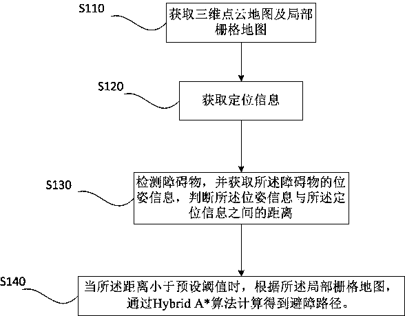
[0059] Please refer to figure 1 As shown, a low-speed unmanned vehicle obstacle avoidance method includes the following steps:

[0060] S110. Obtain a three-dimensional point cloud map and a local grid map;

[0061] The specific method for generating a three-dimensional point cloud map in S110 is not specifically limited in this embodiment, and any method that can generate a three-dimensional point cloud map can be used in step S110.

[0062] The local grid map is a real-time constructed map. The local grid map uses a low-speed unmanned vehicle as the coordinate system and builds a completed local grid map. The loca...

Example Embodiment

[0084] Example two

[0085] The second embodiment is carried out on the basis of the first embodiment, and mainly explains and describes the state polling mechanism of the low-speed unmanned vehicle.

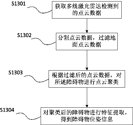
[0086] Specifically, when detecting obstacles, the following steps are included:

[0087] Polling the vehicle state through a finite state machine mechanism, the vehicle state including tracking state, stopping state and obstacle avoidance state;

[0088] When the vehicle state is the tracking state, control the low-speed unmanned vehicle to drive along the global waypoint; detect obstacles in real time and obtain the obstacle pose information, and determine the pose information and the positioning information the distance between;

[0089] When the distance between the pose information and the positioning information is less than a preset threshold, switch the tracking state to the stop state;

[0090] After the obstacle avoidance path is calculated by the Hybrid A* algorithm, switch the...

Example Embodiment

[0102] Example three

[0103] The third embodiment mainly explains and illustrates the specific process of the Hybrid A* algorithm calculating the obstacle avoidance path.

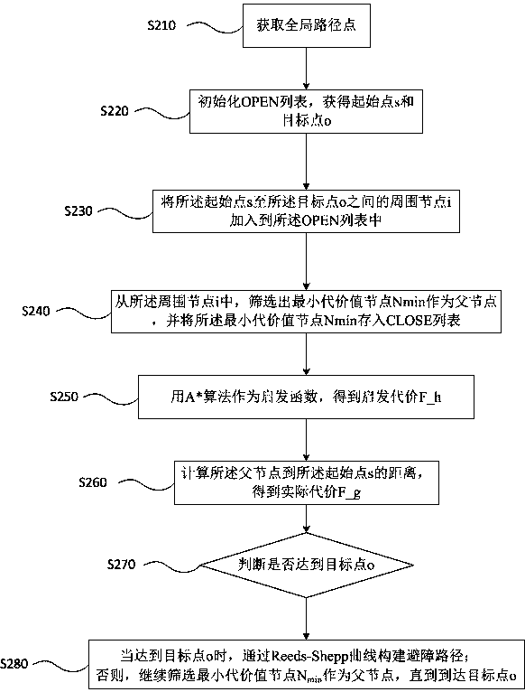
[0104] Please refer to image 3 As shown, when the distance is less than the preset threshold, the obstacle avoidance path is calculated by the Hybrid A* algorithm according to the local grid map, including the following steps:

[0105] S210: Obtain a global path point;

[0106] The above-mentioned global waypoint is a fixed driving route of a low-speed unmanned vehicle in a certain area, such as a park. The global waypoint can be a path obtained by recording or a manually set path reference line.

[0107] S220. Initialize the OPEN list, and obtain a starting point s and a target point o from the global path points, and the starting point s and the target point o are in the local grid map;

[0108] The OPEN list in S220 is a list of stored parameters in the Hybrid A* algorithm. The starting point s is the current po...


PUM


Abstract

The invention discloses a low-speed unmanned vehicle obstacle avoidance method, relates to the technical field of automatic driving, and is used for solving the problem that a low-speed unmanned vehicle motion model is not considered in existing obstacle avoidance. The metod comprises the following steps: acquiring a three-dimensional point cloud map and a local grid map; acquiring positioning information according to the three-dimensional point cloud map; detecting an obstacle, obtaining pose information of the obstacle, and judging the distance between the pose information and the positioning information; and when the distance is smaller than a preset threshold, calculating an obstacle avoidance path through a Hybrid A* algorithm according to the local grid map. The invention further discloses a low-speed unmanned vehicle obstacle avoidance device, electronic equipment and a computer storage medium. The low-speed unmanned vehicle obstacle avoidance method combined with a motion modelis realized through the Hybrid A* algorithm.

Description

technical field [0001] The present invention relates to the technical field of automatic driving, in particular to an obstacle avoidance method, device, equipment and medium for a low-speed unmanned vehicle. Background technique [0002] Low-speed unmanned vehicles mainly refer to self-driving vehicles with relatively simple and fixed application scenarios and low speeds per hour. Their main application scenarios include campuses, scenic spots, parks, airports, mines, etc. Low-speed unmanned vehicles are mainly used for logistics in specific areas Distribution, mining, unmanned agricultural machinery, catering and retail services, etc. [0003] At present, the path planning method of low-speed unmanned vehicles is mainly realized by Dijkstra, A*, D* and D*_lite algorithms. Both D* and its improved D*_lite algorithm can be used to achieve dynamic local obstacle avoidance, but these algorithms None of them take into account the actual kinematic model of the vehicle, lack of j...

Claims


Application Information

Patent Timeline
IPC IPC(8): G05D1/02
CPCG05D1/0257
Inventor 嵇望丁大为马浩
Owner ZHEJIANG UTRY INFORMATION TECH CO LTD
Why Eureka
Try Eureka