Broadband planar reflection antenna and optimization design method based on differential evolution algorithm

A flat-panel reflection and antenna technology, applied in antennas, design optimization/simulation, antenna supports/installation devices, etc., can solve the problems of large material and financial resources, low standing wave, large standing wave ratio, etc., and achieve rich antenna design The effect of experience, small material and financial resources, and small standing waves

Pending Publication Date: 2020-06-26
CHINA UNIV OF GEOSCIENCES (WUHAN)
View PDF0 Cites 0 Cited by
  • Summary
  • Abstract
  • Description
  • Claims
  • Application Information

AI Technical Summary

Problems solved by technology

This design method has the following defects: 1. Antenna designers are required to have solid electromagnetic theory knowledge and rich antenna design experience, which requires relatively high requirements for antenna design practitioners; 2. This antenna design method is inefficient , requiring a large amount of material and financial resources
At present, the performance of the broadband flat reflective antennas used in the prior art is poor, and the standing wave ratio is very large. Therefore, it is necessary to provide a design optimization method to design the parameters of the broadband flat reflective antennas, and at the same time provide a relatively low standing wave broadband planar reflector antenna

Method used


Image

  • Broadband planar reflection antenna and optimization design method based on differential evolution algorithm
  • Broadband planar reflection antenna and optimization design method based on differential evolution algorithm
  • Broadband planar reflection antenna and optimization design method based on differential evolution algorithm

Examples


Embodiment Construction

[0036] In order to have a clearer understanding of the technical features, purposes and effects of the present invention, the specific implementation manners of the present invention will now be described in detail with reference to the accompanying drawings.

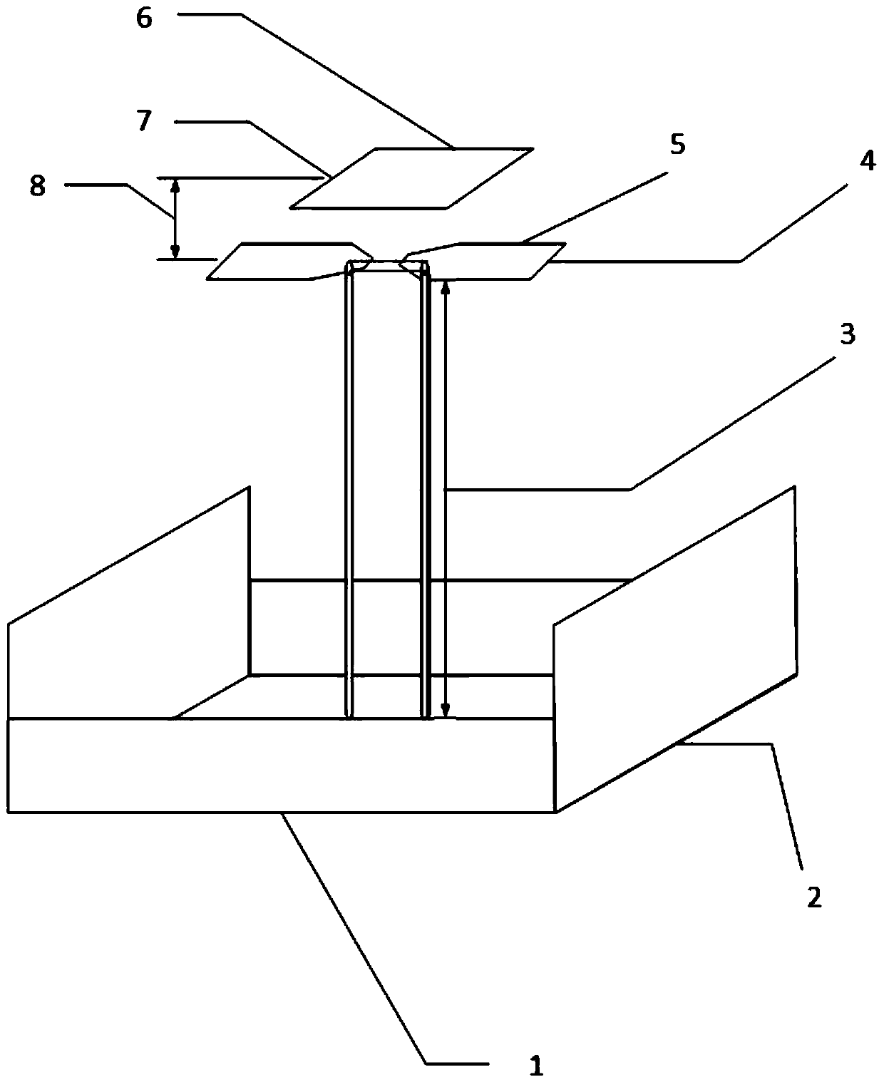
[0037] refer to figure 1 , figure 1 It is a structural schematic diagram of the broadband planar reflective antenna of the present invention. The broad-band planar reflective antenna used in the body includes a rectangular reflective panel at the bottom, a butterfly-shaped radiation panel in the middle, and a rectangular guide panel at the top, which are made of conductive materials;

[0038] The rectangular reflective panel at the bottom includes a rectangular bottom plate and fixed rectangular side plates extending upward along the perimeter of the rectangular bottom plate. The shape and size of the two opposite rectangular side plates on the width of the rectangular bottom plate are the same. and the same size, and...


PUM


Abstract

The invention discloses a broadband planar reflection antenna and an optimization design method based on a differential evolution algorithm. The broadband planar reflection antenna comprises a rectangular reflection panel at the bottom, a butterfly-shaped radiation panel in the middle and a rectangular guide panel at the top which are respectively made of a conductive material, wherein the lengthof the rectangular bottom plate is 667.5 mm minus or plus 3%, and the width is 393 mm minus or plus 3%; the distance between the bottom reflecting plate and the butterfly-shaped radiation panel is 279.7 mm minus or plus 3%, the width of the rectangular part is 175.3 mm minus or plus 3%, and the length of the rectangular part of the butterfly-shaped radiation panel is 183.6 mm minus or plus 3%; thedistance between the butterfly-shaped radiation panel and the rectangular guide panel is 62.3 mm minus or plus 3%, the length of the rectangular guide plate is 237.8 mm minus or plus 3%, and the width of the rectangular guide plate is 202.2 mm minus or plus 3%.

Description

technical field [0001] The invention relates to the field of antenna design, in particular to a wide-band planar reflective antenna and an optimal design method based on a differential evolution algorithm. Background technique [0002] At present, antenna design mainly relies on manual work. When designing a new antenna, antenna design engineers often use electromagnetic theory knowledge combined with their own experience to design the antenna structure type that may meet the requirements according to the design requirements. Part of the parameters are optimized, and the optimization process is often a trial-and-error optimization in a local range. This design method has the following defects: 1. Antenna designers are required to have solid electromagnetic theory knowledge and rich antenna design experience, which requires relatively high requirements for antenna design practitioners; 2. This antenna design method is inefficient , need to consume a lot of material and finan...

Claims


Application Information

Patent Timeline
Patent Type & Authority Applications(China)
IPC IPC(8): H01Q1/36H01Q19/10H01Q1/50H01Q1/12G06F30/20
CPCH01Q1/12H01Q1/36H01Q1/50H01Q19/106
Inventor 曾三友章锐赵菲
Owner CHINA UNIV OF GEOSCIENCES (WUHAN)
Why Eureka
Try Eureka