A hardware socket for an electronic device

A technology of electronic equipment and hardware, applied in the direction of electrical components, parts of connecting devices, circuits, etc., can solve problems such as looseness, poor contact, and easy damage, and achieve the effect of simple structure and reduced displacement difference

Active Publication Date: 2021-11-19
新沂市泰达电子有限公司
View PDF5 Cites 0 Cited by
  • Summary
  • Abstract
  • Description
  • Claims
  • Application Information

AI Technical Summary

Problems solved by technology

[0002] In the traditional cooperation between the slot and the memory stick, if the quality of the slot and the memory stick is unqualified or the slot and the memory stick are worn to a certain extent after long-term use, it will cause looseness between the slot and the memory stick. The contact between the gold finger and the gold finger on the memory stick cannot be sufficiently good, which causes a series of problems in the related electronic equipment
[0003] Moreover, the cooperation between the traditional slot and the memory stick will also loosen under the action of frequent vibrations, resulting in poor contact between the gold fingers on the slot and the gold fingers on the memory stick, and in severe cases, the memory stick will be burned and damaged
In addition, the gold fingers in the traditional slot are deformed by arching outwards to clamp the memory stick inserted into it; since the gold fingers on the slot are always involved in the electrical connection, the gold fingers on the slot will remain in place for a long time. Oxidation occurs after use, and the oxidized gold finger is easily damaged due to its reduced elasticity, resulting in poor contact between the slot and the memory stick
[0004] In view of the above-mentioned problems in traditional slots, it is necessary to design a hardware slot for electrical equipment that can effectively solve the problem of poor contact caused by quality problems, frequent vibration, or aging and oxidation of traditional slots and memory sticks.

Method used


Image

  • A hardware socket for an electronic device
  • A hardware socket for an electronic device
  • A hardware socket for an electronic device

Examples


Embodiment Construction

[0044] The accompanying drawings are all schematic diagrams of the implementation of the present invention, so as to understand the principle of structural operation. The specific product structure and proportional size can be determined according to the use environment and conventional technology.

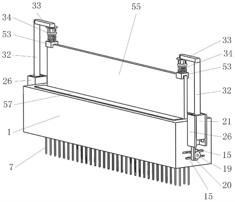
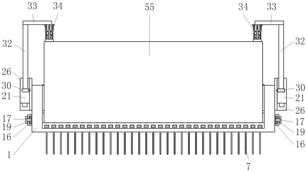
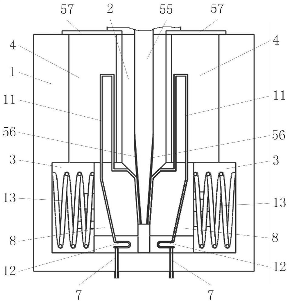
[0045] Such as figure 1 , 2 , 3, it includes socket 1, pin 7, clip bar 8, conductive contact piece A11, spring A13, rack A15, gear A18, gear B19, rack B20, slider 21, round rod 32, pressure Institutions 34, such as image 3 , 8 As shown in , 9, the socket 1 is used to insert the memory stick 55 on the inner wall of the slot 2 of the memory stick 55 and slides symmetrically along the direction perpendicular to the memory stick 55 board. The slopes of the clamping strips 8 are opposite; as image 3 , 9 , 21, a number of conductive contacts A11 are uniformly distributed along the longitudinal direction of each clip bar 8, and several conductive contacts A11 on the clip bar 8 ar...


PUM


Abstract

The invention belongs to the field of hardware slots, in particular to a hardware slot for electronic equipment, which includes a socket, a pin, a clip bar, a conductive contact piece A, a spring A, a rack A, a gear A, a gear B, and a rack B. The slider, the round rod, and the pressure-applying mechanism, wherein on the inner wall of the card slot for inserting the memory stick on the socket, there are two wedge-shaped clamping strips for clamping the memory stick, sliding symmetrically along the direction perpendicular to the memory stick board surface, and The slopes of the two clamping bars face each other; during the relative movement between the memory stick and the two clamping bars due to vibration, the conductive contact B on the memory stick and the conductive contact A on the two clamping bars are misaligned due to mutual friction. The dust adsorbed on the conductive contact piece A and the conductive contact piece B due to long-term use can be effectively cleaned, thereby further ensuring good contact between the memory stick and the conductive contact pieces on the two clamping strips. The conductive contact piece A in the slot in the present invention is not easy to be damaged and failed due to oxidation.

Description

technical field [0001] The invention belongs to the field of hardware slots, in particular to a hardware slot for electronic equipment. Background technique [0002] In the traditional cooperation between the slot and the memory stick, if the quality of the slot and the memory stick is unqualified or the slot and the memory stick are worn to a certain extent after long-term use, it will cause looseness between the slot and the memory stick. The gold finger on the memory stick cannot form a sufficient and good contact with the gold finger on the memory stick, causing a series of problems in related electronic equipment. [0003] Moreover, the cooperation between the traditional slot and the memory stick will also loosen under the action of frequent vibrations, resulting in poor contact between the gold fingers on the slot and the gold fingers on the memory stick, and in severe cases, the memory stick will be burned and damaged . In addition, the gold fingers in the traditio...

Claims


Application Information

Patent Timeline
Patent Type & Authority Patents(China)
IPC IPC(8): H01R13/40H01R13/502H01R13/627H01R13/629
CPCH01R13/40H01R13/502H01R13/627H01R13/629
Inventor 夏天
Owner 新沂市泰达电子有限公司
Why Eureka
Try Eureka