Cooling structure for permanent magnet motor

A technology of cooling structure and permanent magnet motor, which is applied in the direction of cooling/ventilation devices, electrical components, electromechanical devices, etc., which can solve the problems of unable to improve the cooling effect and cumbersome installation, so as to avoid the decline of cooling effect, accelerate the heat dissipation speed, and improve the cooling effect. effect of effect

Inactive Publication Date: 2020-06-26
杭州益众节能环保科技有限公司
View PDF0 Cites 0 Cited by
  • Summary
  • Abstract
  • Description
  • Claims
  • Application Information

AI Technical Summary

Problems solved by technology

[0003] Part of the existing cooling structure for permanent magnet motors is provided with two holes on the stator, one hole inputs the cooling medium, and the other hole outputs the cooling medium, so that the permanent magnets in the rotor are cooled by heat exchange. It is cumbersome to install before use and requires extra energy, and the other part is to install a fan on the inner and rear side of the motor, but the bearing housing covers the rotor and stator, so that the fan can only dissipate heat from the outer wall, so that the cooling effect cannot be improved

Method used


Image

  • Cooling structure for permanent magnet motor
  • Cooling structure for permanent magnet motor
  • Cooling structure for permanent magnet motor

Examples


Embodiment Construction

[0027] The following will clearly and completely describe the technical solutions in the embodiments of the present invention with reference to the accompanying drawings in the embodiments of the present invention. Obviously, the described embodiments are only some, not all, embodiments of the present invention. Based on the embodiments of the present invention, all other embodiments obtained by persons of ordinary skill in the art without creative efforts fall within the protection scope of the present invention.

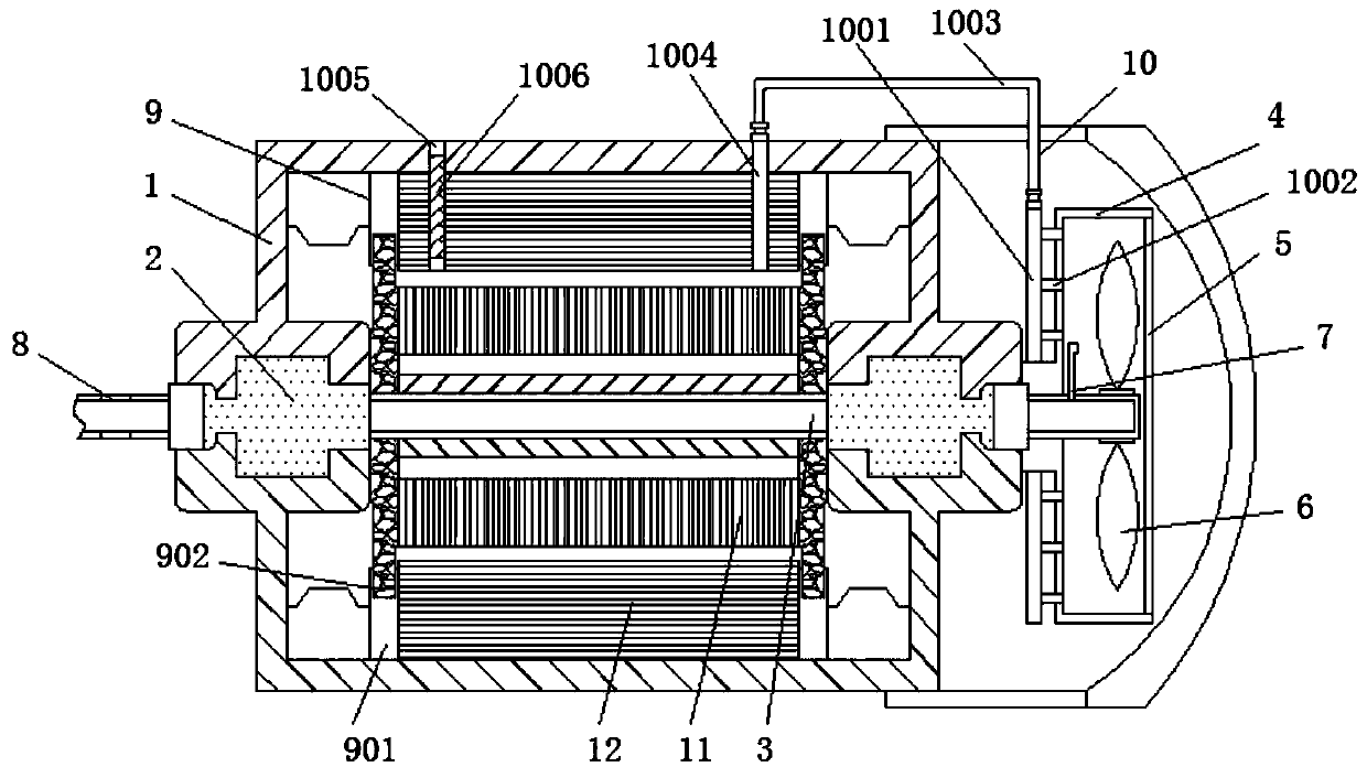
[0028] refer to Figure 1-4 , a cooling structure for a permanent magnet motor, comprising a housing 1, bearings 2 are arranged inside the inner walls of both sides of the housing 1, and an output shaft 3 runs through the interior of the bearing 2 transversely, and a fixed frame is installed on one side of the housing 1 4, and one side of the fixed frame 4 is fixed with a filter sponge net 5, the output shaft 3 runs through the inside of the fixed frame 4, and the ...


PUM


Abstract

The invention discloses a cooling structure for a permanent magnet motor. The invention relates to the technical field of permanent-magnet motor cooling. The cooling structure comprises a shell, bearings are arranged in the inner walls of the two sides of the shell, and an output shaft transversely penetrates through the interiors of the bearings. A fixing frame is installed on one side of the shell, and a filtering sponge net is fixed to one side of the fixing frame. The output shaft penetrates through the interior of the fixing frame, and fan blades are inlaid in the outer wall of one end ofthe output shaft. An air inlet pipe is connected to one side of the upper end of the output shaft, and the air inlet pipe is located in the fixing frame. In the present invention, when the output shaft drives the fan blades to rotate, certain wind can be generated, the wind enters the output shaft from the air inlet pipe and then is exhausted from an air outlet hole in the other side, so that airin the output shaft flows, a rotor and permanent magnets can be cooled from the right middle part, the conventional mode of only cooling from a gap between the rotor and the stator is replaced, the cooling speed of the rotor and the permanent magnets is increased, and the cooling effect is improved.

Description

technical field [0001] The invention relates to the technical field of cooling of permanent magnet motors, in particular to a cooling structure for permanent magnet motors. Background technique [0002] Like DC motors, induction motors, etc., permanent magnet motors are also composed of three parts: stator, rotor and auxiliary devices. There are three-phase AC windings on the stator and excitation windings on the rotor. After the DC current is applied, it can generate a magnetic field. During the working process of the magneto, it is necessary to adopt forced heat dissipation measures to take away the heat inside the permanent magnet synchronous motor, so as to avoid the demagnetization phenomenon caused by the permanent magnet inside the rotor due to long-term high temperature working environment, so it is necessary to provide a cooling mechanism in the permanent magnet motor . [0003] Part of the existing cooling structure for permanent magnet motors is provided with two...

Claims


Application Information

Patent Timeline
Patent Type & Authority Applications(China)
IPC IPC(8): H02K9/10H02K9/06
CPCH02K9/06H02K9/10
Inventor 顾建平顾春恋
Owner 杭州益众节能环保科技有限公司
Why Eureka
Try Eureka