Automatic brushing device for corrosion protective agent
A technology for corrosion protection and driving device, which can be applied to devices and coatings that apply liquid to surfaces, and can solve problems such as low painting efficiency
- Summary
- Abstract
- Description
- Claims
- Application Information
AI Technical Summary
Problems solved by technology
Method used
Image

Examples
Embodiment
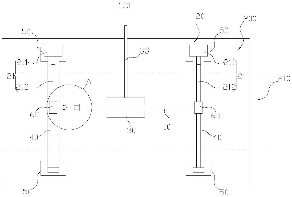
[0048]The embodiment of the present application provides an automatic application device 100 for corrosion protection agent, which can effectively improve the efficiency and quality of application of corrosion protection agent on the splash and tidal range area 210 of the steel wall 200 .
[0049] Such as figure 1 As shown, the implementation of the present application provides a corrosion protection agent automatic brushing device 100, which is used to paint corrosion corrosion protection agent on the steel wall 200. The device includes a connecting beam 10, a driving device 20, a brushing head 30 and two vertical Rail 40.
[0050] The two vertical guide rails 40 are arranged on the steel wall 200 at intervals. One end of the connecting beam 10 is movably arranged on one vertical guide rail 40 , and the other end is movably arranged on the other vertical guide rail 40 . The driving device 20 is used to drive the connecting beam 10 to move vertically; the brushing head 30 is...
PUM
 Abstract
Description
Claims
Application Information
PatSnap Eureka turns technology decisions into work you can execute. Powered by our Innovation Knowledge Graph, it runs expert workflows across engineering, life sciences, materials and intellectual property. Get your review-ready output in minutes.


