Glue dispensing device for hole wall

A glue dispensing device and glue dispensing technology, applied to the surface coating liquid device, coating, etc., can solve the problems of low production efficiency, heavy labor, slow manual operation, etc., and achieve simple structure, energy saving, and compensation The effect of market gaps

Pending Publication Date: 2020-06-30
SUZHOU LANGKUN AUTOMATION EQUIP CO LTD
View PDF0 Cites 1 Cited by
  • Summary
  • Abstract
  • Description
  • Claims
  • Application Information

AI Technical Summary

Problems solved by technology

[0002] The positive and negative concave pads need to be installed on the lithium battery cover. In order to ensure the installation strength and insulation, it is necessary to apply insulating glue to the mounting hole of the concave pad on the cover. Currently, the dispensing glue on the market is aimed at the outer wall, and there is no one for the inner wall of the hole on the market. The glue-applying machine can only be operated manually, which is slow and labor-intensive. After the glue is applied, it needs to be air-dried, and it can be stored in a centralized manner after air-drying. This requires multiple positioning of the product, and the production efficiency is low. Based on The above defects and deficiencies, it is necessary to improve the existing technology, design a kind of hole wall with dispensing device

Method used


Image

  • Glue dispensing device for hole wall
  • Glue dispensing device for hole wall
  • Glue dispensing device for hole wall

Examples


Embodiment Construction

[0013] The preferred embodiments of the present invention will be described in detail below in conjunction with the accompanying drawings, so that the advantages and features of the invention can be more easily understood by those skilled in the art, so as to define the protection scope of the present invention more clearly.

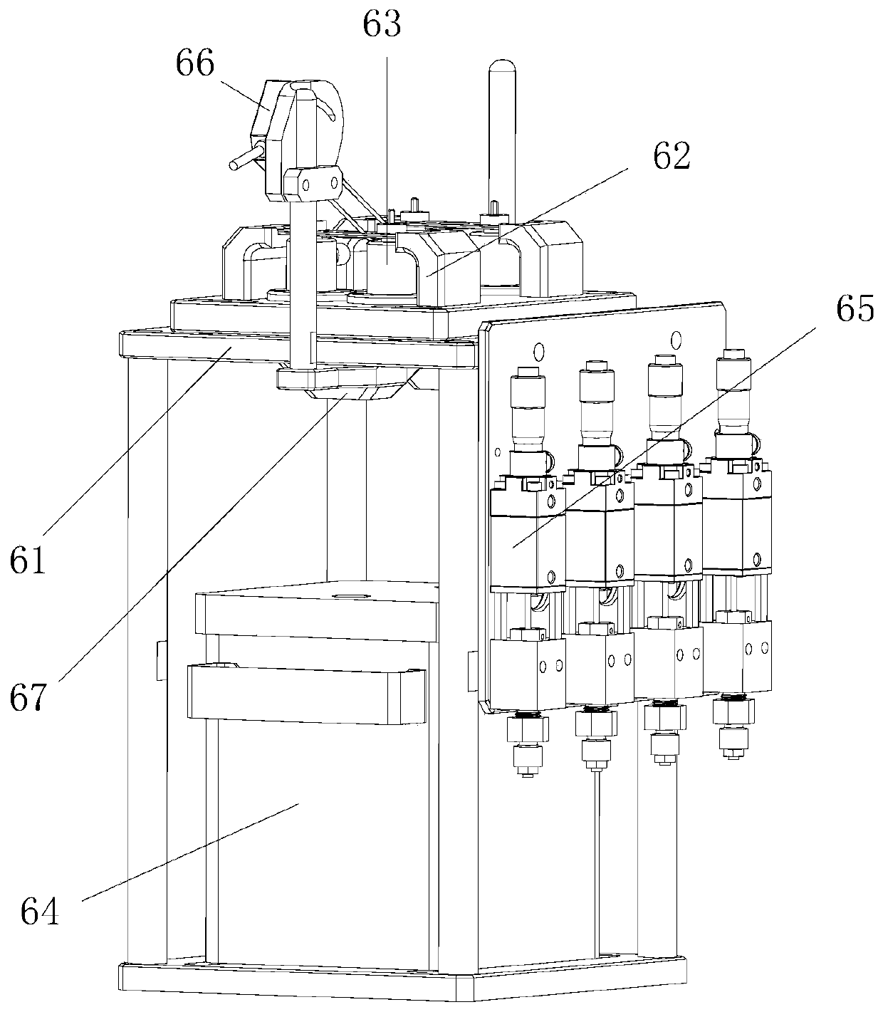
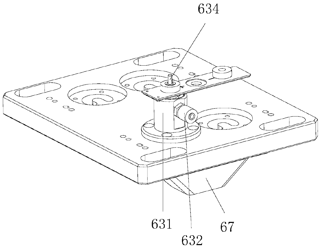
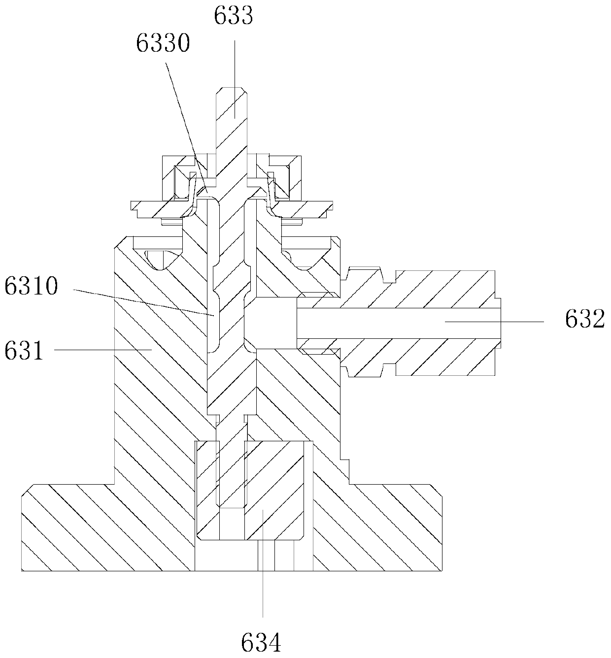
[0014] see Figure 1 to Figure 5 , the embodiment of the present invention includes:

[0015] A glue dispensing device for a hole wall, which includes a glue dispensing bracket 61, a cover plate fixing block 62, a glue dispensing head 63, a glue bucket 64, a quantitative glue valve 65, a glue dispensing sensor 66 and a recovery block 67. Two sets of cover plate fixing blocks 62 are installed on the top plate of the dispensing bracket 61, and a cover plate is placed on the upper end of a set of cover plate fixing blocks 62, and two sets of concave pads are arranged on the dispensing bracket 61 below the cover plate. The installation hole matches the disp...


PUM


Abstract

The invention discloses a glue dispensing device for a hole wall. The glue dispensing device for the hole wall comprises a glue dispensing support, cover plate fixing blocks, glue dispensing heads, aglue barrel, quantitative glue valves, a glue dispensing sensor and a recovery block. A top plate of the glue dispensing support is provided with two groups of cover plate fixing blocks, a cover plateis placed at the upper ends of an opposite group of cover plate fixing blocks, and the two glue dispensing heads matched with concave pad installation holes are arranged on the glue dispensing support below the cover plate; the glue barrel and the quantitative glue valves are arranged on a bottom plate and at the side end of the glue dispensing support, and the glue barrel is connected to feed ports of the glue dispensing heads through the quantitative glue valves; the glue dispensing sensor is further arranged at the side end of the glue dispensing support, the glue dispensing sensor pointsto an upper cover plate of the cover plate fixing blocks; and the recovery block communicating with return ports in the bottoms of the glue dispensing heads is installed at the bottom of the top plateof the glue dispensing support, and a return port of the recovery block is connected to the glue barrel through a pipeline. Through the method, the structure of the glue dispensing device for the hole wall is simple, the glue dispensing device can apply insulating glue around the hole wall, the market gap is filled, the surplus insulating glue can be recovered, and the energy is saved.

Description

technical field [0001] The invention relates to the technical field of mechanical assembly, in particular to a glue dispensing device for hole walls. Background technique [0002] The positive and negative concave pads need to be installed on the lithium battery cover. In order to ensure the installation strength and insulation, it is necessary to apply insulating glue to the mounting hole of the concave pad on the cover. Currently, the dispensing glue on the market is aimed at the outer wall, and there is no one for the inner wall of the hole on the market. The glue-applying machine can only be operated manually, which is slow and labor-intensive. After the glue is applied, it needs to be air-dried, and it can be stored in a centralized manner after air-drying. This requires multiple positioning of the product, and the production efficiency is low. Based on Above defect and deficiency, it is necessary to improve existing technology, design a kind of hole wall and use dispen...

Claims


Application Information

Patent Timeline
Patent Type & Authority Applications(China)
IPC IPC(8): B05C7/00B05C5/02B05C11/10B05C13/02
CPCB05C5/02B05C5/0225B05C7/00B05C11/10B05C11/1026B05C11/1039B05C13/02Y02P70/10
Inventor 金磊谭祖斌郑贵军
Owner SUZHOU LANGKUN AUTOMATION EQUIP CO LTD
Why Eureka
Try Eureka