Supercharge Your Innovation With Domain-Expert AI Agents!

A batch marking equipment for plastic bottle caps

A technology of marking equipment and bottle caps, applied in welding equipment, plastic recycling, laser welding equipment, etc., can solve the problems of low efficiency, low safety, manual placement and manual removal, etc., to achieve the effect of easy access

Active Publication Date: 2022-06-07
莆田市涵江区智荣电子有限公司
View PDF0 Cites 0 Cited by
  • Summary
  • Abstract
  • Description
  • Claims
  • Application Information

AI Technical Summary

Problems solved by technology

[0004] At present, there are some relatively simple small plastic bottle cap marking machines in the market. Due to its simple structure, when marking, the user needs to manually place the plastic bottle cap at the marking position, and after marking, it needs to be manually Taking out the plastic bottle cap is not only inefficient, but also less safe
[0005] Based on the above-mentioned problems in the marking of plastic bottle caps, it is necessary to design a batch marking machine for plastic bottle caps that can be automatically placed and automatically taken out to overcome the above shortcomings of manual placement and manual removal of plastic bottle caps.

Method used


Image

  • A batch marking equipment for plastic bottle caps
  • A batch marking equipment for plastic bottle caps
  • A batch marking equipment for plastic bottle caps

Examples


Embodiment 1

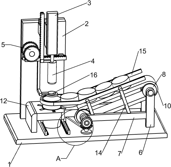
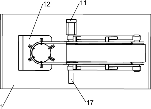
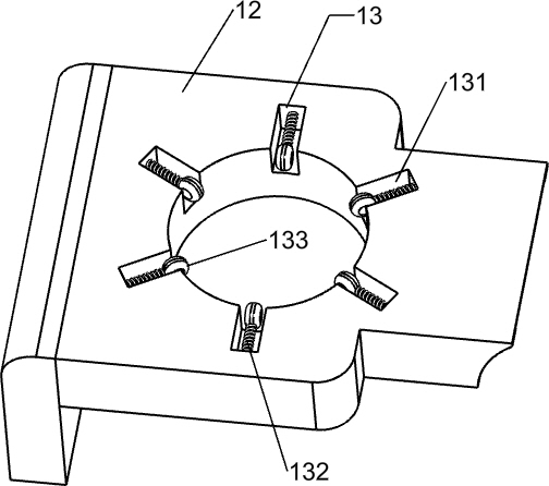
[0025] A kind of plastic bottle cap batch marking equipment, such as Figure 1-6Shown, including the base 1, mounting plate 2, cylinder 3, push rod 4, moving mechanism 5, the first bracket 6, the second bracket 7, the first conveyor wheel 8, the second conveyor wheel 9, conveyor belt 10, servo motor 11, the third bracket 12, the support mechanism 13, the fourth bracket 14, the fence 15 and the laser marking machine 16, the base 1 top left rear side with mounting plate 2, the mounting plate 2 front side of the upper part of the mobile mechanism 5, the mobile mechanism 5 lower part with laser marking machine 16, the mounting plate 2 front side upper part with cylinder 3, Cylinder 3 is located on the right side of the moving mechanism 5, cylinder 3 is equipped with a pushrod 4, the top of the push rod 4 is connected to the moving mechanism 5, the base 1 is provided with a first bracket 6 on the top right side, the first bracket 6 is equipped with a first conveyor wheel 8, the first br...

Embodiment 2

[0032] On the basis of Example 1, e.g., Figure 7Shown, further comprising a connecting shaft 17, a first bevel gear 18, a second housing 19, a second shaft 20, a second bevel gear 21 and a lever 22, a second conveyor wheel 9 is provided with a connecting shaft 17 on the front side, a connection shaft 17 is provided with a first bevel gear 18 on the front side, a second bearing housing 19 is provided on the left side of the base 1 top, a second bearing housing 19 is located under the first bevel gear 18, the first bevel gear 18 is mounted with a second shaft 20, and the second shaft 20 is provided with a second bevel gear 21, The second bevel gear 21 engages the first bevel gear 18, and the second shaft 20 is provided with a lever 22.

[0033] The second conveyor wheel 9 rotates through the connecting shaft 17 to drive the first bevel gear 18 rotation, the first bevel gear 18 turns to drive the second bevel gear 21 to rotate, the second bevel gear 21 rotates through the shaft to dr...


PUM


Abstract

The invention relates to a marking device, in particular to a batch marking device for plastic bottle caps. Therefore, the technical problem of the present invention is to provide a batch marking machine for plastic bottle caps that can be automatically placed and automatically taken out when marking plastic bottle caps. A batch marking equipment for plastic bottle caps, comprising: a base, the base is used to support the whole equipment; a mounting plate, the mounting plate is set on the top side of the base; The inner upper part of the installation plate; the push rod, the push rod is arranged at the lower part of the cylinder; the moving mechanism, the moving mechanism is arranged at the inner upper part of the installation plate. The invention achieves the effect of automatically placing and taking out the marked plastic bottle caps. The conveyor belt will drive the plastic bottle caps to the marking position without manual placement. The cylinder will push the plastic bottle caps down to the base through the push rod. , easy for staff to take.

Description

Technical field [0001] The present invention relates to a marking device, in particular to a plastic bottle cap batch marking equipment. Background [0002] Marking refers to the production, in accordance with the relevant provisions of the state or the company's own management needs, on the product text, pictures and other identification, such as: production date, expiration date, product number and so on. This process is called marking. [0003] Marking machine is divided into many kinds, the most common are pneumatic marking machine, electromagnetic marking machine, electrochemical marking machine, laser marking machine, laser marking machine is the use of high-energy laser in a variety of metal non-metallic surface non-contact permanent marking, such as identification model, logo, coding, text, etc., in the existing field, often encounter the case of marking on the bottle cap, such as plastic bottle caps, etc. [0004] At present, there are some relatively simple small plasti...

Claims


Application Information

Patent Timeline
Patent Type & Authority Patents(China)
IPC IPC(8): B41J3/407B23K26/362B23K26/402B23K26/70
CPCB23K26/362B23K26/402B23K26/702B23K2103/42Y02W30/62
Inventor 不公告发明人
Owner 莆田市涵江区智荣电子有限公司
Features
  • R&D
  • Intellectual Property
  • Life Sciences
  • Materials
  • Tech Scout
  • Unparalleled Data Quality
  • Higher Quality Content
  • 60% Fewer Hallucinations
Learn More