Buffer displacement mechanism of laser cutting machine

A laser cutting machine and buffer displacement technology, which is applied in laser welding equipment, welding equipment, metal processing equipment, etc., can solve the problems of affecting cutting progress, cutting head vibration, and long Y-axis moving track, so as to achieve strong practicability and improve Air Quality Effects

Active Publication Date: 2020-06-30
安徽汉超智能装备科技有限公司
View PDF7 Cites 0 Cited by
  • Summary
  • Abstract
  • Description
  • Claims
  • Application Information

AI Technical Summary

Problems solved by technology

In order to improve the cutting efficiency, the laser cutting head needs to move at a high speed. Among them, the moving track of the Y-axis is longer. When moving to both ends at high speed and contacting the limit block, it is easy to generate a large impact force. This impact force is easy to make the cutting head Vibration will affect the cutting progress

Method used


Image

  • Buffer displacement mechanism of laser cutting machine
  • Buffer displacement mechanism of laser cutting machine
  • Buffer displacement mechanism of laser cutting machine

Examples


Embodiment 1

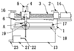
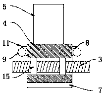
[0028] refer to figure 1 , image 3 and Figure 4 , a buffer displacement mechanism of a laser cutting machine, comprising a cutting machine table 1, the bottom of the cutting machine table 1 is provided with a frame plate 13, and the right side of the cutting machine table 1 is provided with a servo motor 14 coupled with a laser cutting machine numerical control box , the two ends of the upper surface of the cutting machine table 1 are provided with limit blocks 2, and the same drive screw 3 is connected between the two limit blocks 2 through bearing rotation, and the surface of the drive screw 3 is provided with a lateral shock-absorbing displacement Block 4, the upper surface of the transverse damping displacement block 4 is provided with an X-axis cutting frame 5, and a screw nut 15 is arranged between the transverse damping displacement block 4 and the driving screw mandrel 3, and the screw nut 15 and the transverse damping displacement block 4 fixed connection.

[002...

Embodiment 2

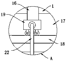
[0034] refer to figure 1 , figure 2 and Figure 5 , different from Embodiment 1, the front side of the transverse damping displacement block 4 is fixedly connected with the connecting rod 16 located at the front side of the cutting machine table 1, and the front side of the cutting machine table 1 has a movable hole 17, and the front side of the cutting machine table 1 is located at the The bottom of the movable hole 17 is provided with a movable flat plate 18, and the bottom of the connecting rod 16 is fixedly connected with a dust-absorbing stick box 19 which passes through the movable hole 17 and is positioned at the X-axis cutting frame 5 below. The bottom of the dust-absorbing stick box 19 is provided with a The rolling wheel on the movable flat plate 18 top, the upper surface of the dust-absorbing bar box 19 offers a plurality of dust-absorbing holes 20 .

[0035] The front of the frame plate 13 is provided with a fan box 21, and the inside of the fan box 21 is provid...


PUM


Abstract

The invention discloses a buffer displacement mechanism of a laser cutting machine. The buffer displacement mechanism comprises a cutting machine table, wherein limiting blocks are arranged at the twoends of the upper surface of the cutting machine table, the same driving screw rod is rotatably connected between the two limiting blocks through a bearing, a transverse damping displacement block isarranged on the surface of the driving screw rod in a sleeving mode, an X-axis cutting frame is arranged on the upper surface of the transverse damping displacement block, buffer mechanisms are arranged on the upper surface of the cutting machine table and the inside of the transverse damping displacement block separately, and automatic buffer components extending to two sides of the transverse damping displacement block are arranged in the transverse damping displacement block. According to the mechanism, magnetic attraction is generated by arranging a magnetic plate and a deceleration magnet, so that the mechanism has the deceleration effect, and magnetic force is gradually increased, so that strong collision between the side surfaces of the transverse damping displacement block and thelimiting blocks is avoided; and meanwhile, the buffer mechanisms consisting of negative pressure balls are arranged, so that inflation and deflation of the negative pressure balls are driven by selfmotion, and the inflated negative pressure balls make contact with the limiting blocks, so that the mechanism has the buffering and damping effects.

Description

technical field [0001] The invention relates to the technical field of laser cutting machines, in particular to a buffer displacement mechanism of a laser cutting machine. Background technique [0002] Laser cutting is to focus the laser emitted from the laser into a high power density laser beam through the optical path system. The laser beam irradiates the surface of the workpiece to make the workpiece reach the melting point or boiling point, and at the same time, the high-pressure gas coaxial with the beam blows away the molten or vaporized metal. With the movement of the relative position of the beam and the workpiece, the material will eventually form a slit, so as to achieve the purpose of cutting. There are existing research and development and application of energy-saving technology for heating and residential buildings. [0003] During the cutting process, the laser cutting head needs to move in the X-axis and Y-axis directions according to the generated graphics....

Claims


Application Information

Patent Timeline
Patent Type & Authority Applications(China)
IPC IPC(8): B23K26/70B23K26/142B23K26/38
CPCB23K26/38B23K26/142B23K26/702
Inventor 陈宏
Owner 安徽汉超智能装备科技有限公司
Why Eureka
Try Eureka