Concrete finished product hopper combined discharge valve

A discharge valve and concrete technology, which is applied in the direction of cleaning hollow objects, clay preparation devices, control devices, etc., can solve the problems of inconsistent height, falling on the ground, and splashing of concrete slurry, so as to improve fluidity and reduce stickiness. Attachment, the effect of avoiding waste

Pending Publication Date: 2020-06-30
NANJING XILONG MASCH EQUIP CO LTD
View PDF0 Cites 2 Cited by
  • Summary
  • Abstract
  • Description
  • Claims
  • Application Information

AI Technical Summary

Problems solved by technology

At present, most of the discharge valves at the bottom of the finished hopper are straight cylinders. When unloading, the concrete slurry moves vertically downward into a free-falling body and enters the concrete mixer truck, causing the concrete slurry to splash when unloading, and the splashed part falls. Outside the body of the concrete mixer truck; when the material is unloaded quickly, part of the concrete slurry will overflow the hopper of the transport vehicle and fall to the ground, causing environmental pollution
Moreover, the height of concrete mixer trucks is inconsistent, some are as high as 4.2m, some are as low as 3.8m, and the drop is as high as 400mm. It will make part of the concrete slurry splash when unloading. Therefore, there is an urgent need for a discharge valve that can solve the above problems.

Method used


Image

  • Concrete finished product hopper combined discharge valve
  • Concrete finished product hopper combined discharge valve
  • Concrete finished product hopper combined discharge valve

Examples


Embodiment Construction

[0025] Specific embodiments of the present invention will be described below in conjunction with the accompanying drawings.

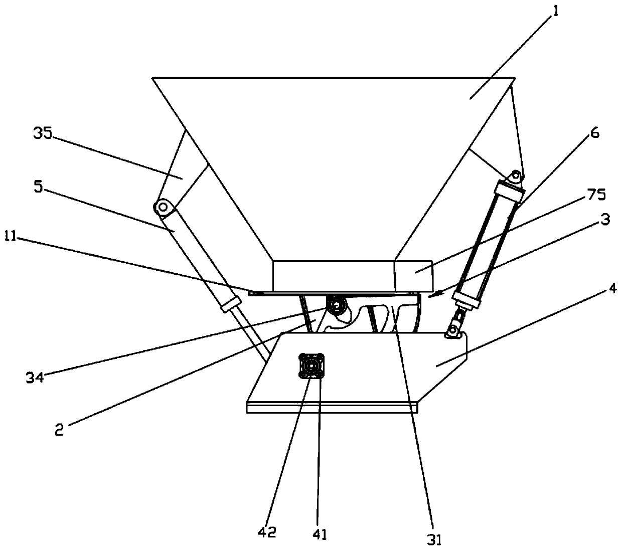
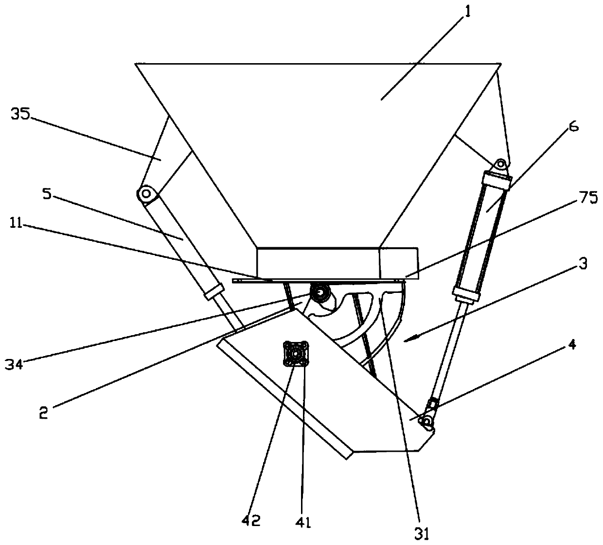
[0026] Such as Figure 1-7 As shown, it is a combined unloading valve for a concrete finished hopper in this embodiment, which includes a raw material hopper 1 and a vertical unloading valve 2 arranged up and down in sequence. The bottoms are all open, the lower end of the raw material hopper 1 is connected with the top of the vertical discharge valve 2 through the flange 11, and the outer peripheral side of the vertical discharge valve 2 is provided with an arc-shaped valve plate 3 and a movable Chute 4, arc valve plate 3 comprises left side plate 31, right side plate 32 and arc bottom plate 33, left side plate 31 and right side plate 32 are fan-shaped hollow structures, the circle center of left side plate 31 and right side plate 32 Each of them is connected to the opposite outer wall of the vertical discharge valve 2 through the rotating shaft 34 re...


PUM


Abstract

The invention provides a concrete finished product hopper combined discharge valve, and relates to the technical field of discharge valves. The concrete finished product hopper combined discharge valve comprises a raw material hopper and a vertical discharge valve which are sequentially arranged up and down, the raw material hopper is in the shape of an inverted circular truncated cone, both the top and the bottom of the vertical discharge valve are open, the lower end of the raw material hopper is connected with the top of the vertical discharge valve through a flange, an arc-shaped valve plate and a movable chute are sequentially arranged on the peripheral side of the vertical discharge valve from inside to outside, the arc-shaped valve plate comprises a left side plate, a right side plate and an arc-shaped bottom plate, the left side plate and the right side plate are both of fan-shaped hollowed-out structures, the circle centers of the left side plate and the right side plate are rotationally connected to the opposite outer walls of the vertical discharge valve through rotating shafts, the arc-shaped bottom plate is arranged between an arc-shaped edge of the left side plate andan arc-shaped edge of the right side plate and located at the bottom of the vertical discharge valve. The concrete finished product hopper combined discharge valve has the advantages that the phenomena of slurry leakage and material leakage when the discharge valve is closed can be avoided, concrete slurry splashing can be avoided when concrete mixers of different heights are fed, and the like.

Description

technical field [0001] The invention relates to the technical field of unloading valves, in particular to a combined unloading valve for concrete finished buckets. Background technique [0002] The function of the finished hopper loading and unloading valve is to load the concrete slurry in the finished hopper into the concrete mixer truck through the control unloading valve. At present, most of the discharge valves at the bottom of the finished hopper are straight cylinders. When unloading, the concrete slurry moves vertically downward into a free-falling body and enters the concrete mixer truck, causing the concrete slurry to splash when unloading, and the splashed part falls. Outside the body of the concrete mixer truck; when the material is unloaded quickly, part of the concrete slurry will overflow the hopper of the transport vehicle and fall to the ground, causing environmental pollution. Moreover, the height of concrete mixer trucks is inconsistent, some are as high ...

Claims


Application Information

Patent Timeline
Patent Type & Authority Applications(China)
IPC IPC(8): B28C5/08B28C5/16B28C7/02B08B9/087
CPCB08B9/087B28C5/0806B28C5/0818B28C5/0862B28C5/16B28C7/02
Inventor 孙敬民
Owner NANJING XILONG MASCH EQUIP CO LTD
Why Eureka
Try Eureka