
Injection mold machining table

A technology of injection mold and processing table, applied in the direction of work table, manufacturing tool, etc., can solve the problems of inconvenient cleaning of debris, accumulation of debris, inconvenient adjustment of the angle of injection mold, etc., to achieve convenient fixed work, Easy to operate and avoid loose effect

Inactive Publication Date: 2020-06-30
芜湖裕优机械科技有限公司
View PDF2 Cites 4 Cited by
  • Summary
  • Abstract
  • Description
  • Claims
  • Application Information

AI Technical Summary

Problems solved by technology

[0006] The object of the present invention is to provide a kind of injection mold processing table, in order to solve the problem that the current injection mold processing table on the market proposed by the above-mentioned background technology is not convenient enough to clean the debris generated during processing, and the debris is easy to fall off. After entering the interior of the processing table, they are piled up together, and at the same time, it is not convenient to adjust the angle of the injection mold after clamping

Method used


Image

  • Injection mold machining table
  • Injection mold machining table
  • Injection mold machining table

Examples


Embodiment Construction

[0029] The following will clearly and completely describe the technical solutions in the embodiments of the present invention with reference to the accompanying drawings in the embodiments of the present invention. Obviously, the described embodiments are only some, not all, embodiments of the present invention. Based on the embodiments of the present invention, all other embodiments obtained by persons of ordinary skill in the art without making creative efforts belong to the protection scope of the present invention.

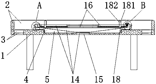
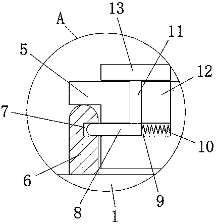
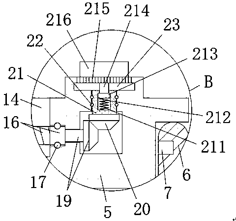
[0030] see Figure 1-8 , the present invention provides a technical solution: an injection mold processing table, including a base 1, an outer frame 2 and a third ball 22, the top surface of the base 1 is welded and fixed with the outer frame 2, and the base 1 is provided with a discharge groove 3, and the base 1 is connected to the support seat 5 through the first ball 4, the support seat 5 and the limit ring 6 are connected to each other, and the limit ring ...


PUM


Abstract

The invention discloses an injection mold machining table. The injection mold machining table comprises a base, an outer frame and a third ball, wherein the outer frame is welded and fixed to the topface of the base, and a discharging groove is formed in the base; the base is connected with a supporting seat through a first ball, the supporting seat is connected with a limiting ring, and the limiting ring is welded and fixed to the limiting ring; and a limiting hole is formed in the limiting ring, the limiting ring is connected with a limiting shaft, and the limiting shaft is arranged insidea first storage groove; and the first storage groove is formed inside the supporting seat, and a connecting spring is arranged inside the first storage groove. According to the injection mold machining table, chippings generated during machining can be blocked through the outer frame arranged on the base, meanwhile, workers can subsequently clear the chippings on the base through the discharging groove in the base, and after the chippings fall into a second storage groove, the chippings can be discharged through a through hole, so that the chippings are prevented from being accumulated insidethe second storage groove.

Description

technical field [0001] The invention relates to the technical field of molds, in particular to an injection mold processing table. Background technique [0002] The mold is mainly composed of different parts. It mainly realizes the processing of the shape of the object through the change of the physical state of the molded material. At the same time, in the process of industrial production, the types of molds are different through different methods, including injection molding. Mold, when processing the injection mold, it is necessary to use a processing table, but the existing injection mold processing table still has the following deficiencies; [0003] 1. In the process of processing the injection mold, the debris produced is not easy to clean, and at the same time, it is easy to make the debris slide into the inside of the processing table, so that in the long run, the debris is easy to accumulate inside the processing table. It affects the overall operation of the proc...

Claims


Application Information

Patent Timeline
Patent Type & Authority Applications(China)
IPC IPC(8): B29C33/38B25H1/08B25H1/10B25H1/12
CPCB25H1/08B25H1/10B25H1/12B29C33/3842
Inventor 不公告发明人
Owner 芜湖裕优机械科技有限公司
Learn More