Mechanical supercharger

A mechanical supercharger and blade technology, applied in mechanical equipment, machines/engines, rotary piston machines, etc., can solve the problems of connection, inability to close the profile, low compression, etc., to improve the diameter to distance ratio, improve the use Power and rotational torque, and the effect of improving the area utilization factor

Pending Publication Date: 2020-06-30
JIANGSU SAILIN AUTOMOBILE TECH CO LTD
View PDF0 Cites 3 Cited by
  • Summary
  • Abstract
  • Description
  • Claims
  • Application Information

AI Technical Summary

Problems solved by technology

[0003] At present, the rotor of a supercharger usually adopts a three-lobed or four-lobed structure, and the profiles of the two intermeshing rotors are consistent. The ratio of the diameter of the outer circle of the rotor to half the center distance of the two rotors is called the diameter-to-spacing ratio), such as Figure 4 It shows a traditional four-lobed structure, the center position of the peak circle 100 and the valley circle 200 is fixed, and must be located at the intersection of the base circle 300 and the long and short axes of the airfoil. To increase the diameter-to-spacing ratio of the two rotors , while the diameter of the outer circle of the rotor remains unchanged, the center distance between the two rotors needs to be reduced, so the radius of the base circle is decreasing. At this time, the positions of the centers of the peak circle 100 and the valley circle 200 change, which cannot be compared with the involute Therefore, for the linear structure of the three-lobe or four-lobe body, the maximum diameter-to-spacing ratio of the three-lobe rotor can only be taken as 1.46, and the area utilization coefficient is 0.49. The maximum diameter-to-spacing ratio can only be 1.36, and the area utilization coefficient is only 0.43, and the area utilization coefficient of the two rotors cannot be increased by increasing the diameter-to-spacing ratio of the two rotors. If the area utilization coefficient is low, the compression degree of the two rotors to the air will be low. Therefore, the torque of the existing supercharger to drive the engine is only 240Nm

Method used


Image

  • Mechanical supercharger
  • Mechanical supercharger
  • Mechanical supercharger

Examples


Embodiment approach

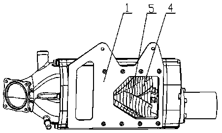
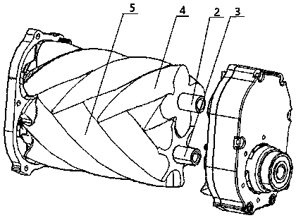
[0033] Such as Figure 1 to Figure 3 An embodiment of a supercharger of the present invention is shown, including a supercharger housing 1 and a first rotating shaft 2 and a second rotating shaft 3 placed in the supercharger housing 1, the first rotating shaft The first rotor mechanism 4 is set on the top of the 2, and the second rotor mechanism 5 is set on the second rotating shaft 3. The first rotor mechanism 4 and the second rotor mechanism 5 mesh with each other as the first rotating shaft 2 and the second rotating shaft 3 rotate. ;

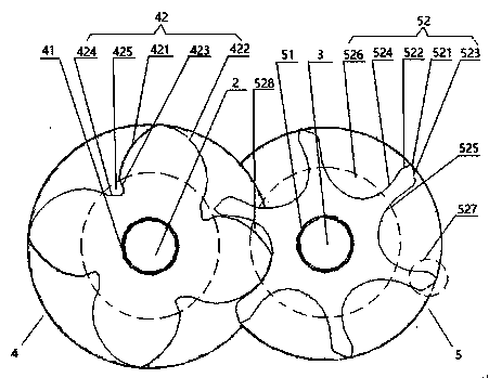
[0034] The first rotor mechanism 4 includes a first rotor body 41 and a plurality of first blades 42 protruding outwards placed on the first rotor body 41, the plurality of first blades 42 are evenly distributed, and the plurality of first blades 42 are formed by the first One end of the rotor body 41 extends to the other end to form a helical structure, and the first blade 42 includes a left involute 421, a right involute 422, a left root 4...


PUM


Abstract

The invention relates to a mechanical supercharger. The mechanical supercharger comprises a mechanical supercharger shell, and a first rotating shaft and a second rotating shaft which are arranged inthe mechanical supercharger shell; the first rotating shaft is sleeved with a first rotor mechanism, and the second rotating shaft is sleeved with a second rotor mechanism; the first rotor mechanism comprises a first rotor body and multiple of first blades arranged on the first rotor body and protruding outwards, and the first blades comprise left involutes, right involutes, left root lines and right root lines; and the second rotor mechanism comprises a second rotor body and multiple of second blades arranged on the second rotor body and protruding outwards, and the second blades comprise topcircular lines, left extending lines, right extending lines, left arc lines and right arc lines. The supercharger has the following advantages that the area utilization coefficient of two rotors is increased by increasing the radius-center distance ratio of the two rotors, so that the use power and the rotation torque of an engine are improved.

Description

Technical field: [0001] The invention belongs to the field of automobile supercharging, and in particular relates to a mechanical supercharger. Background technique: [0002] Engine supercharging technology can greatly increase the power and torque of the engine without increasing the cylinder volume. The supercharger is a double-rotor compression machine driven by gears. And the process cycle of the three processes of exhaust. The supercharger is a rotary machine, and the two intermeshing rotors are the most important rotating parts. The end faces of the rotors linearly affect the overall performance of the supercharger. [0003] At present, the rotor of a supercharger usually adopts a three-lobed or four-lobed structure, and the profiles of the two intermeshing rotors are consistent. The ratio of the diameter of the outer circle of the rotor to half the center distance of the two rotors is called the diameter-to-spacing ratio), such as Figure 4 It shows a traditional fo...

Claims


Application Information

Patent Timeline
Patent Type & Authority Applications(China)
IPC IPC(8): F04C18/16F04C29/00C22C23/00C22C1/02
CPCC22C1/02C22C23/00F04C18/084F04C18/16F04C2240/20
Inventor 卢兆强马德志鲁骏裘晓灵郑斌谢棋吴超胜
Owner JIANGSU SAILIN AUTOMOBILE TECH CO LTD
Why Eureka
Try Eureka