
An assembly device and assembly method of an accelerometer excitation ring assembly

A technology for accelerometers and assembly devices, which is applied in the direction of connecting components, material gluing, mechanical equipment, etc., to achieve the effects of improving assembly efficiency, reducing impact, and eliminating quality hazards

Active Publication Date: 2021-12-31
航天科工惯性技术有限公司
View PDF7 Cites 0 Cited by
  • Summary
  • Abstract
  • Description
  • Claims
  • Application Information

AI Technical Summary

Problems solved by technology

[0003] The purpose of the present invention is to propose an assembly device and an assembly method for an accelerometer excitation ring assembly, which can effectively improve production efficiency and improve the accuracy of the accelerometer. reliability

Method used


Image

  • An assembly device and assembly method of an accelerometer excitation ring assembly
  • An assembly device and assembly method of an accelerometer excitation ring assembly
  • An assembly device and assembly method of an accelerometer excitation ring assembly

Examples


Embodiment 1

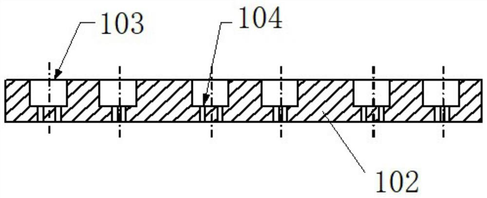
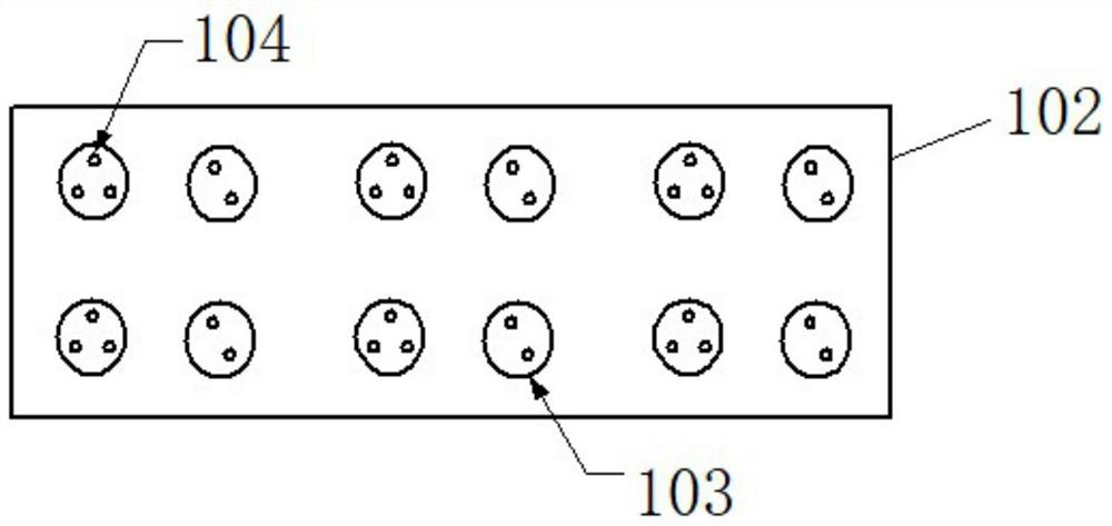
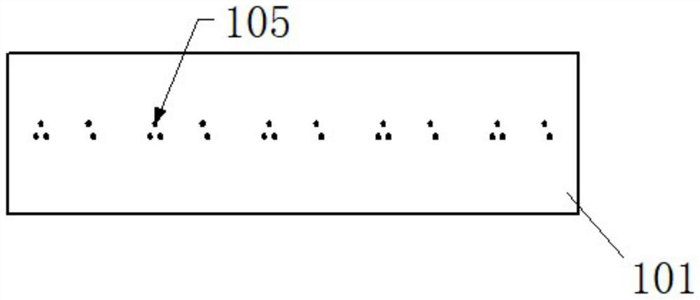
[0029] refer to Figure 1-Figure 3 , this embodiment provides an assembly device for an accelerometer excitation ring assembly, including a terminal assembly manufacturing tooling and a positioning plate 101;

[0030] The tooling for making the terminal assembly includes a tooling main body 102, a plurality of glue filling holes 103 are arranged on the tooling main body 102, and a first positioning hole 104 is arranged on the bottom surface of the glue filling holes 103;

[0031] Multiple sets of second positioning holes 105 are disposed on the positioning plate 101 .

[0032] As a preferred embodiment, the glue filling hole 103 is a counterbore, and the outer diameter of the glue filling hole 103 is slightly smaller than the assembly through hole of the excitation ring.

[0033] As a preferred embodiment, the depth of the glue filling hole 103 matches the depth of the assembly through hole of the excitation ring.

[0034] As a preferred implementation manner, the depth of t...

Embodiment 2

[0039] refer to Figure 4 , this embodiment provides an assembly method of the accelerometer excitation ring assembly, which is assembled by using the assembly device of the accelerometer excitation ring assembly as described in Embodiment 1. For the assembly device of the accelerometer excitation ring assembly, please refer to Embodiment 1. This will not be repeated here.

[0040] The methods include:

[0041] Step S201, installing the terminal in the first positioning hole;

[0042] Step S202, filling the glue hole with adhesive;

[0043] Step S203, curing the adhesive to form a terminal assembly;

[0044] Step S204, taking out the terminal assembly, and installing the terminal assembly in the second positioning hole;

[0045] Step S205, coating the adhesive in the assembly through hole of the excitation ring;

[0046] Step S206 , aligning the assembly through hole of the excitation ring with the adhesive on the terminal assembly, and curing the adhesive in the assembly...


PUM


Abstract

The invention provides an assembly device and method for an accelerometer excitation ring assembly. The device includes: a tooling for making a terminal assembly and a positioning plate. The tooling for making a terminal assembly includes a main body of the tooling. The bottom surface of the glue hole is provided with the first positioning hole; the positioning plate is provided with multiple sets of second positioning holes; this device can effectively improve the assembly efficiency of the excitation ring and the terminal, reduce the influence of human factors on the assembly quality, and eliminate the adhesive inside the product The hidden quality hazards caused by residues can improve the overall production capacity of the accelerometer and the reliability of the product.

Description

technical field [0001] The invention relates to the technical field of accelerometer assembly, in particular to an assembly device and an assembly method of an accelerometer excitation ring assembly. Background technique [0002] The excitation ring assembly of the quartz flexible accelerometer is composed of the excitation ring and the binding post connected by adhesive. It is mainly used to provide electrical connection inside the accelerometer and ground the internal components of the accelerometer. It is an important part of the accelerometer. At present, the bonding of the excitation ring and the terminal is usually achieved by manually pouring the adhesive. After the installation of the excitation ring and the terminal is completed, the assembly efficiency of the terminal and the excitation ring is required to be high, and the terminals are insulated from each other. The adhesive between the excitation ring is evenly distributed and the bonding is firm. However, due t...

Claims


Application Information

Patent Timeline
Patent Type & Authority Patents(China)
IPC IPC(8): F16B11/00
CPCF16B11/006
Inventor 刘洋杨守安杨杏敏徐国栋周峰潘天鹏彭福英于湘涛韩旭付秀娟张吉
Owner 航天科工惯性技术有限公司
Learn More