Analysis system for electrical equipment faults

An electrical equipment and analysis system technology, applied in the direction of measuring electricity, measuring electrical variables, measuring devices, etc., can solve problems such as increasing the reliability of equipment fault monitoring, inability to accurately analyze equipment data, and inability to early warning of equipment safe running time.

Active Publication Date: 2020-06-30
AVIC POWER SCI & TECH ENG
View PDF7 Cites 21 Cited by
  • Summary
  • Abstract
  • Description
  • Claims
  • Application Information

AI Technical Summary

Problems solved by technology

[0004] The purpose of the present invention is to provide an analysis system for electrical equipment faults. The electrical equipment information collected by the acquisition module is received by the receiving unit and classified and marked. The equipment analysis module performs data analysis according to the results of the classified marks, thereby analyzing Calculate the electric power difference, the maximum temperature difference and the forward time difference to solve the problem that the equipment data cannot be accurately analyzed in the prior art, increase the accuracy of data analysis, improve the persuasiveness of the data, save analysis time, and improve Work efficiency, through the determination module to analyze the relevant data acquired by the equipment monitoring module and the equipment analysis module, so as to calculate the relevant data, determine whether the equipment is worn or faulty, and calculate the remaining time of the normal operation of the equipment based on the relevant data, and issue a corresponding alarm signal to solve the problem in the prior art that it is impossible to give early warning to the safe running time of the equipment, increase the reliability of equipment failure monitoring, avoid equipment damage, reduce economic losses, increase the safety of the device, and improve the efficiency of fault detection

Method used


Image

  • Analysis system for electrical equipment faults
  • Analysis system for electrical equipment faults
  • Analysis system for electrical equipment faults

Examples


Embodiment Construction

[0034] The following will clearly and completely describe the technical solutions in the embodiments of the present invention with reference to the accompanying drawings in the embodiments of the present invention. Obviously, the described embodiments are only some, not all, embodiments of the present invention. Based on the embodiments of the present invention, all other embodiments obtained by persons of ordinary skill in the art without creative efforts fall within the protection scope of the present invention.

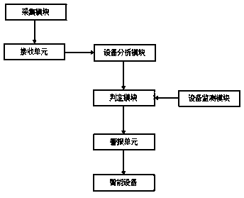
[0035] see Figure 1-3 As shown, the present invention is an analysis system for electrical equipment faults, including an acquisition module, a receiving unit, an equipment analysis module, a judgment module, an equipment monitoring module, an alarm unit and an intelligent device;

[0036] The collection module is used to collect electrical equipment information and transmit it to the receiving unit, and the receiving unit receives the electrical equipment informa...


PUM


Abstract

The invention discloses an analysis system for electrical equipment faults. The analysis system comprises an acquisition module, a receiving unit, an equipment analysis module, a judgment module, an equipment monitoring module, an alarm unit and intelligent equipment; and the acquisition module is used for acquiring electrical equipment information and transmitting a signal to the receiving unit,and the receiving unit receives the electrical equipment information, and performs marking treatment. The specific marking treatment process comprises the following steps: 1, acquiring the electricalequipment information. Related data acquired by the equipment monitoring module and the equipment analysis module are analyzed through the judgment module, related data are calculated, whether the equipment is worn or fails is judged, the remaining time of normal operation of the equipment is determined according to the related data, and a corresponding alarm signal is sent out, so the reliabilityof equipment failure monitoring is improved, equipment damage is avoided, economic losses are reduced, the safety of the device is improved, and the failure detection efficiency is improved.

Description

technical field [0001] The invention relates to the technical field of electrical equipment fault analysis, in particular to an analysis system for electrical equipment faults. Background technique [0002] Electrical equipment is a general term for generators, transformers, power lines, circuit breakers and other equipment in the power system. The important role played by electricity in our life and production cannot be ignored. It brings us great convenience and becomes our The production of important energy in life, the most critical factor in the power plant to allow the normal operation and transmission of electricity is electrical equipment, and electrical equipment occasionally fails during normal use. [0003] When the existing electrical equipment fails, usually when the equipment fails to operate normally, the corresponding technicians will control the equipment to stop running, and then perform fault detection, which is time-consuming and leads to low work efficie...

Claims


Application Information

Patent Timeline
Patent Type & Authority Applications(China)
IPC IPC(8): G01R31/00G01D21/02G08B21/24
CPCG01D21/02G01R31/00G08B21/24
Inventor 金维国刘瑞峰曹磊
Owner AVIC POWER SCI & TECH ENG
Why Eureka
Try Eureka