LED support, LED luminescent device and LED display screen

A technology for LED brackets and light-emitting devices, which is applied to semiconductor devices, instruments, electrical components, etc., can solve the problems of lack of protection for welding sections, reduce the versatility of light-emitting devices, and deformation, so as to promote welding effects and avoid direct heating. Yellowing, The effect of widening the range of application

Pending Publication Date: 2020-06-30
FOSHAN NATIONSTAR OPTOELECTRONICS CO LTD
View PDF0 Cites 0 Cited by
  • Summary
  • Abstract
  • Description
  • Claims
  • Application Information

AI Technical Summary

Problems solved by technology

However, when this side light-emitting device is in use, its welding section is prone to fall off due to lack of protection.
There is no light-emitting device that can emit light from the front and side, which reduces the versatility of the light-emitting device
Moreover, when the existing side light-emitting device is performing wire bonding, it is necessary to heat the chip placement section of the metal pin. The bottom, so as to transfer the heat to the chip placement section, but because the side opposite the chip placement section of the base is generally a plastic component, it is easy to deform and turn yellow at high temperature, which reduces the stability of the product

Method used


Image

  • LED support, LED luminescent device and LED display screen
  • LED support, LED luminescent device and LED display screen
  • LED support, LED luminescent device and LED display screen

Examples


Embodiment 1

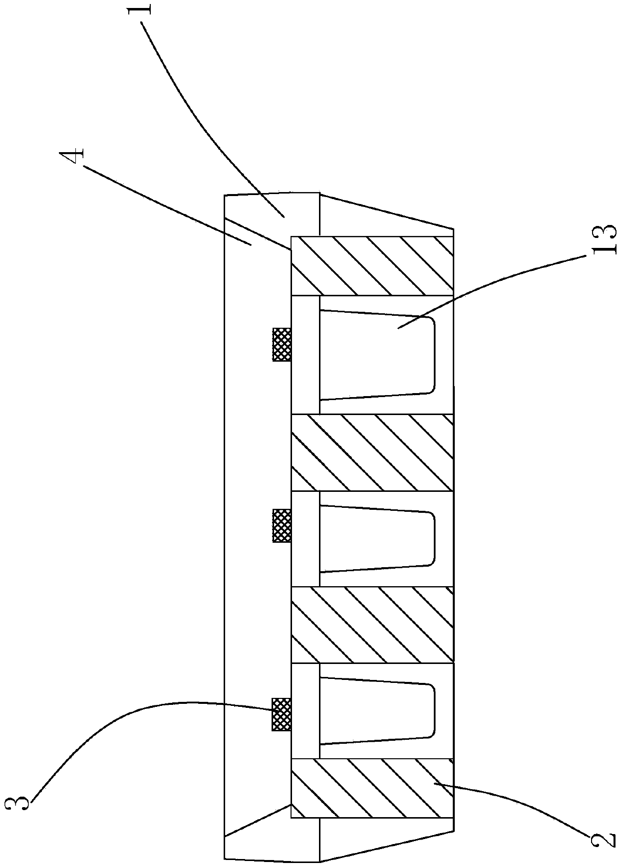
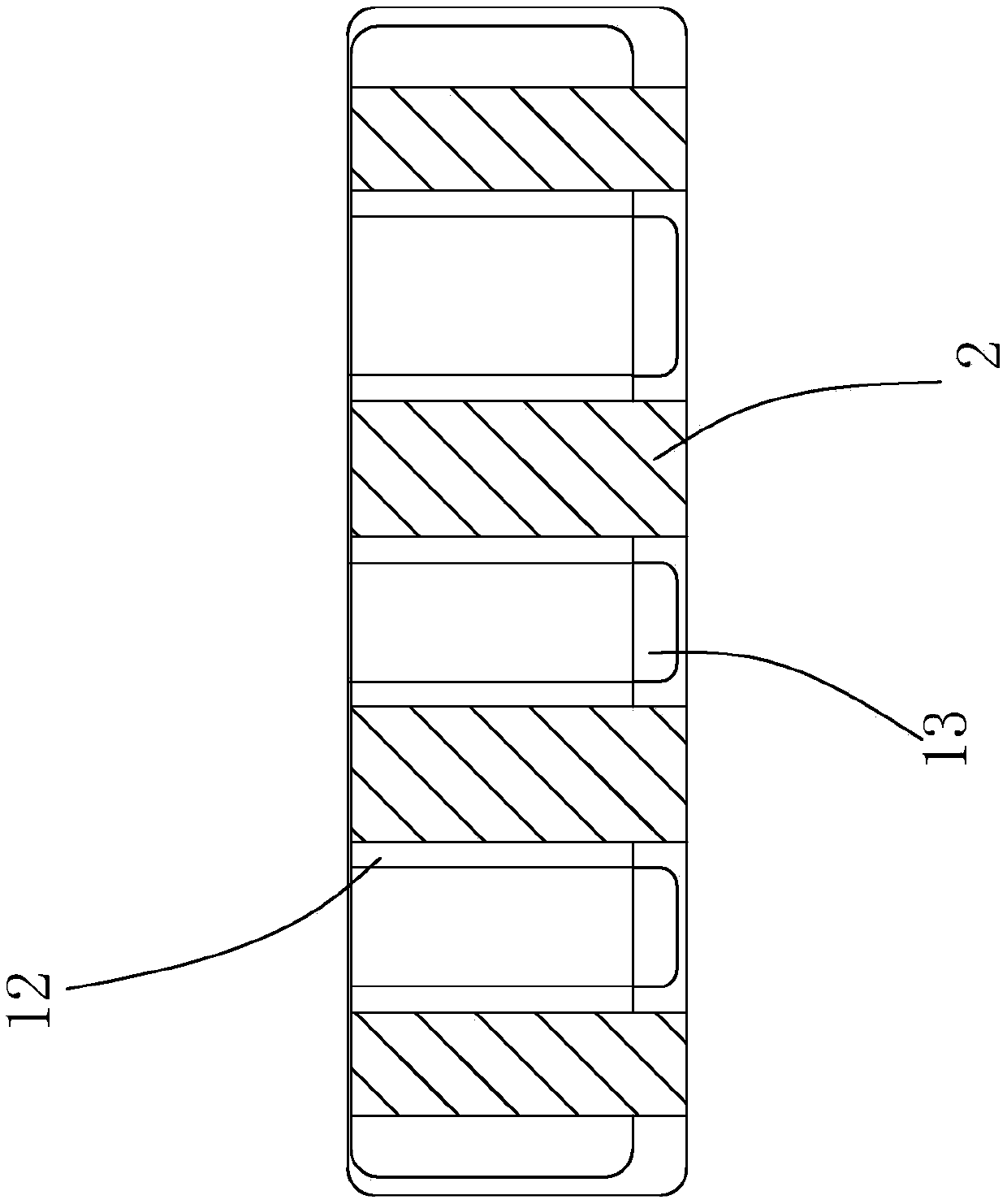
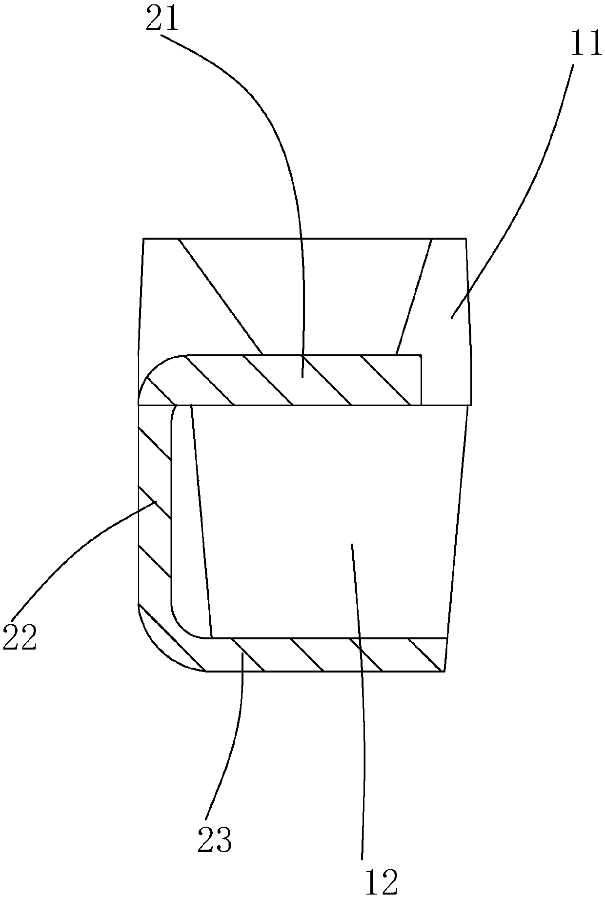
[0024] Example 1: Reference Figure 1 ~ Figure 3 , An LED bracket, comprising a cup cover 1, a metal pin 2, the cup cover 1 including a reflective cup 11, a base 12, the metal pin 2 has more than two, the metal pin 2 includes chip placement Section 21, the vertical welding section 22 and the horizontal welding section 23, all the vertical welding sections 22 of the metal pins 2 are located on the same side of the cup cover 1, and the upper end of the vertical welding section 22 is connected to the chip placement section 21 The lower end is connected to the horizontal welding section 23, the chip placement section 21 is located in the reflector cup 11, the vertical welding section 22 is located outside the side surface of the base 12, and the horizontal welding section 23 is located on the bottom surface of the base 12. Down side.

[0025] By arranging all the vertical welding sections on the same side of the cup cover, when the device is used for side-emitting light, the vertica...

Embodiment 2

[0030] Example 2: see Figure 4 When there are four metal pins, two of the metal pins will be located on the outermost side of the cup cover. As a further preferred embodiment, the base 12 further includes an external partition 14, the external partition 14 Located on the outermost side of the side, that is, on the side of the outermost metal pin. That is to say, an external barrier is provided at each of the two edges of the cup cover to prevent the outermost metal pins from falling off. There should also be a gap between the external barrier and the metal pins, and the range of the gap is also 0.02mm- 0.2mm, preferably 0.08mm-0.12mm.

Embodiment 3

[0031] Example three, see Figure 5 , The side of the base 12 provided with the vertical welding section 22 is a first side, the base 12 also includes a second side opposite to the first side, and the metal pin 2 also includes a balance Section 24, the balance section 24 is located at the end of the horizontal welding section 23, and the balance section 24 is located on the second side surface of the base 12. There can also be a barrier between two adjacent balance sections, or a barrier between two adjacent balance sections and between two adjacent horizontal welding sections, or between two adjacent balance sections. Barriers are set between the balance sections, between two adjacent horizontal welding sections and between two adjacent vertical welding sections to block the left and right deviation of the metal pins and improve product stability. In a more preferred embodiment, an external barrier is also provided beside the outermost balance section of the base to prevent th...


PUM


Abstract

The invention discloses an LED support capable of emitting light from two sides. The LED support comprises a cup cover and metal pins. The cup cover comprises a reflection cup and a base. The number of the metal pins is more than two, all the metal pins are arranged at the same side of the cup cover; each metal pin comprises a chip placing section, a vertical welding section and a horizontal welding section, the chip placing section is arranged in the reflection cup, the vertical welding section is arranged at the outer side of the side surface of the base, and the horizontal welding section is arranged at the lower side of the bottom surface of the base. Meanwhile, the invention further provides an LED luminescent device and an LED display screen using the support. According to the invention, the metal pins of the original side light-emitting device are lengthened and bent and thus the tail ends of the metal pins can be arranged on the bottom surface of the base, so that the LED device is compatible with a side surface-mounted lamp and a back surface-mounted lamp; and the metal pins with good heat-conducting properties are arranged on the bottom surface of the base, so that the defects that the base is heated to become yellow and the stability of a product is influenced are overcome.

Description

Technical field [0001] The present invention relates to the technical field of LEDs, in particular LED supports, light emitting devices and display screens. Background technique [0002] The light-emitting end surface of the chip in the currently used LED components (that is, the plane with the maximum light intensity of the LED chip as the normal line) and the welding plane of its metal pins are either parallel to each other (can be regarded as an angle of 0°) or perpendicular to each other ( That is, the included angle is 90°). When the welding plane of the light-emitting end face and the metal pin are parallel to each other, it is used as a front light-emitting device. The metal pins are arranged on the left and right sides of the bracket, and the metal pins generally include a chip placement section, a connection section and a welding section. The welding section and the chip placement section are parallel to each other; and when the welding plane of the light-emitting end f...

Claims


Application Information

Patent Timeline
Patent Type & Authority Applications(China)
IPC IPC(8): H01L33/62G09F9/33
CPCG09F9/33H01L33/62
Inventor 陈鸿欣肖诗豪肖田易梦骥陈红文林伟建刘传标秦快
Owner FOSHAN NATIONSTAR OPTOELECTRONICS CO LTD
Why Eureka
Try Eureka