A kind of vacuum blood collection tube processing equipment
A technology for vacuum blood collection tubes and processing equipment, which is applied in the field of vacuum blood collection tubes processing equipment, and can solve problems such as complicated processes
- Summary
- Abstract
- Description
- Claims
- Application Information
AI Technical Summary
Problems solved by technology
Method used
Image
Examples
specific Embodiment approach 1
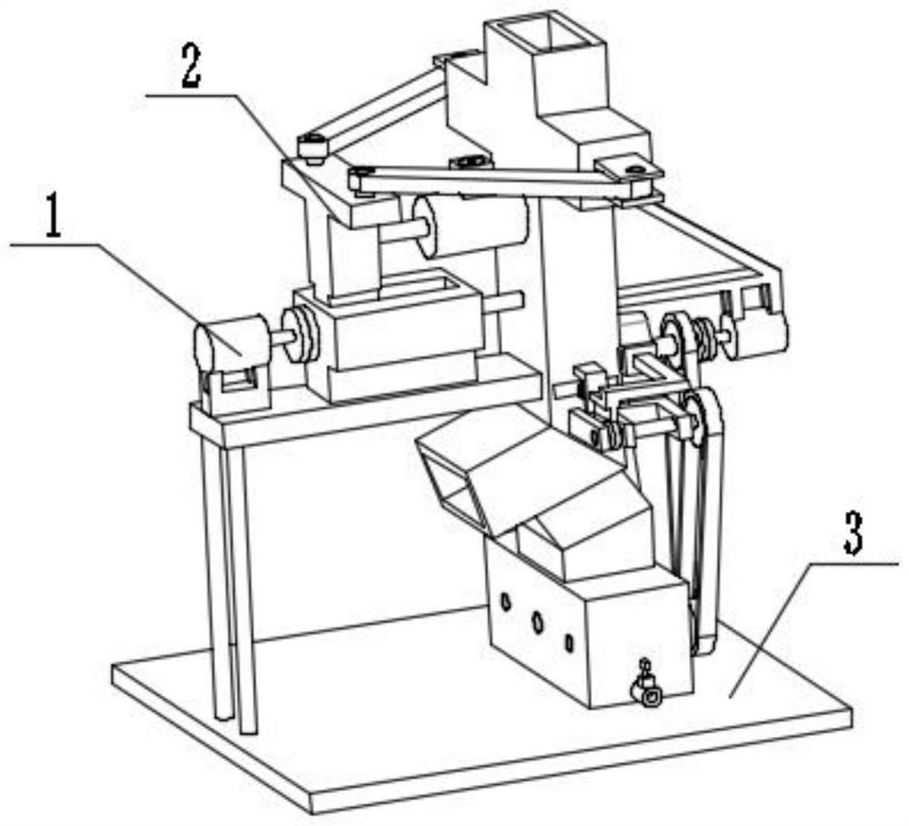
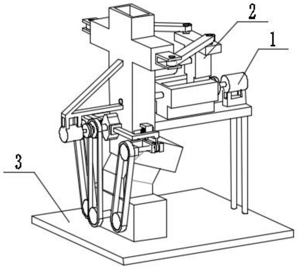
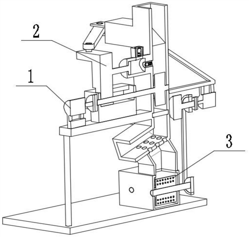
[0029] Combine below figure 1 , figure 2 , image 3 , Figure 4 , Figure 5 , Image 6 , Figure 7 , Figure 8 , Figure 9 , Figure 10 , Figure 11 , Figure 12 , Figure 13 , Figure 14 Describe this embodiment, the present invention relates to a blood collection tube processing equipment, more specifically a vacuum blood collection tube processing equipment, including crushing box mechanism 1, linkage mechanism 2, filter mechanism 3, the equipment can perform intermittent feeding, the equipment It can be crushed and sprayed for disinfection while feeding. The equipment can separate the blood collection tube fragments from the disinfectant waste, and the equipment can better stir and filter the disinfectant waste.
[0030] The crushing box mechanism 1 is connected with the linkage mechanism 2 , and the crushing box mechanism 1 is connected with the filtering mechanism 3 .
specific Embodiment approach 2
[0032] Combine below figure 1 , figure 2 , image 3 , Figure 4 , Figure 5 , Image 6 , Figure 7 , Figure 8 , Figure 9 , Figure 10 , Figure 11 , Figure 12 , Figure 13 , Figure 14Describe this embodiment, this embodiment will further explain the first embodiment, the crushing box mechanism 1 includes a leg 1-1, a support seat 1-2, a servo motor 1-3, a coupling 1-4, a screw 1-5, inlet pipe 1-6, inlet hole 1-7, liquid inlet check valve 1-8, casing 1-9, inlet 1-10, side sliding hole 1-11, door opening and closing mechanism 1- 12. Bearing seat 1-13, bearing seat I1-14, corner support with square hole 1-15, door slot 1-16, liquid outlet 1-17, debris outlet 1-18, leakage hole 1-19, Crushing wheel 1-20, liquid spray check valve 1-21, liquid spray hole 1-22, sliding channel 1-23, support leg 1-1 is connected with support seat 1-2, support seat 1-2 is connected with servo motor 1 -3 connected, the servo motor 1-3 is connected with the coupling 1-4, the coupling 1...
specific Embodiment approach 3
[0034] Combine below figure 1 , figure 2 , image 3 , Figure 4 , Figure 5 , Image 6 , Figure 7 , Figure 8 , Figure 9 , Figure 10 , Figure 11 , Figure 12 , Figure 13 , Figure 14 Describe this embodiment, this embodiment will further explain the first embodiment, the linkage mechanism 2 includes a stepped slider seat 2-1, a threaded hole 2-2, an articulated arm 2-3, an articulated seat 2-4, a sliding Column 2-5, wedge baffle 2-6, piston rod 2-7, piston 2-8, stepped groove I2-9, bearing seat B2-10, sliding support seat I2-11, with stepped slider seat 2- 1 is provided with a threaded hole 2-2, the threaded hole 2-2 is threadedly connected with the lead screw 1-5, the hinged arm 2-3 is hinged with the hinged seat 2-4, and the hinged seat 2-4 is connected with the sliding column 2-5 , the sliding column 2-5 is slidably connected with the side sliding hole 1-11, the sliding column 2-5 is connected with the wedge baffle 2-6, the wedge baffle 2-6 is slidably co...
PUM
 Abstract
Description
Claims
Application Information
 - R&D
- Intellectual Property
- Life Sciences
- Materials
- Tech Scout
- Unparalleled Data Quality
- Higher Quality Content
- 60% Fewer Hallucinations
Browse by: Latest US Patents, China's latest patents, Technical Efficacy Thesaurus, Application Domain, Technology Topic, Popular Technical Reports.
© 2025 PatSnap. All rights reserved.Legal|Privacy policy|Modern Slavery Act Transparency Statement|Sitemap|About US| Contact US: help@patsnap.com


