Check patentability & draft patents in minutes with Patsnap Eureka AI!

Pattern drying device for sand mold casting

A sand casting and drying device technology, which is applied to casting molding equipment, casting molds, cores, etc., can solve the problems of loss of coating on the surface of the pattern, impact on the quality of casting products, and easy knotting on the drying rack, etc., to improve coating quality. Efficiency and coating uniformity, ensuring drying quality, ensuring the effect of uniformity and reliability

Active Publication Date: 2020-07-03
ANHUI XUANTONG IND DESIGN CO LTD
View PDF7 Cites 0 Cited by
  • Summary
  • Abstract
  • Description
  • Claims
  • Application Information

AI Technical Summary

Problems solved by technology

When implementing pattern production, it is necessary to use a spraying machine to carry out a full range of spraying operations on a single or a certain number of patterns, and after the spraying is completed, they are placed on the drying rack respectively, and then the rapid drying operation is performed. After the pattern is placed on the drying rack and dried, the pattern product can be obtained for subsequent casting. When the above pattern is produced, it is difficult to achieve uniform coverage in actual spraying, and when the spraying is finished There is also a relatively serious hang phenomenon in the pattern. After being placed directly on the drying rack, the paint falls on the drying rack after the paint is placed on the drying rack. When the pattern is taken out of the drying rack, it will dry The paint is easy to get stuck on the drying rack, causing serious paint loss on the surface of the pattern, which has a great impact on the quality of subsequent casting products

Method used


Image

  • Pattern drying device for sand mold casting
  • Pattern drying device for sand mold casting
  • Pattern drying device for sand mold casting

Examples


Embodiment Construction

[0033] In order to make the objects and advantages of the present invention clearer, the present invention will be described in detail below in conjunction with the examples. It should be understood that the following words are only used to describe one or several specific implementation modes of the present invention, and do not strictly limit the protection scope of the specific claims of the present invention. As used herein, the terms "parallel" and "perpendicular" are not limited to their strict geometric definitions, but include reasonable and inconsistent tolerances for machining or human error;

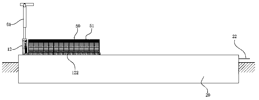
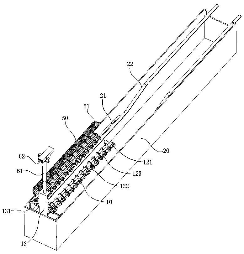
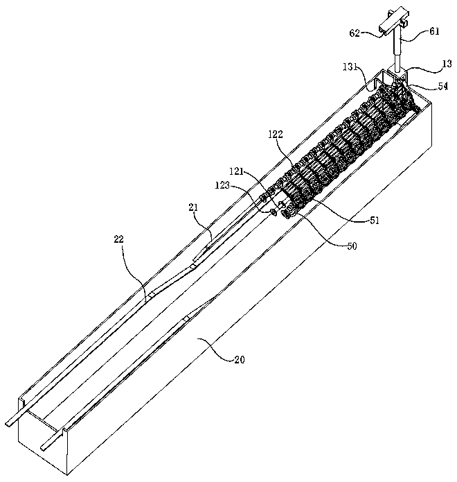
[0034] Attached below Figure 1 to Figure 24 , the vacuum casting model glue coating system of the present invention is described in detail:

[0035] The pattern drying device for sand casting of the present invention will be described in detail below in conjunction with the entire vacuum casting pattern glue coating system:

[0036] A vacuum casting model glue coating syste...


PUM


Abstract

The invention relates to a pattern drying device for sand mold casting. The pattern drying device comprises a drying frame used for bearing a pattern, a moving mechanism drives the drying frame to belocated in a drying room for drying operation, the drying frame comprises a bottom material receiving rod and material receiving rods on two sides, and the material receiving rods and the material receiving rods on two sides are wrapped with films correspondingly; the positions of the material receiving rods and the material receiving rods on two sides correspond to the position of a coating bracket; when the coating bracket moves to the position of the drying frame, the bottom material receiving rod and a lower supporting rod are staggered, the material receiving rods on two sides and the supporting rods on the two sides are staggered, and therefore the whole pattern can be transferred to the drying frame so as to complete transferring of the pattern. The bottom material receiving rod and the material receiving rods on two sides are wrapped with the films, the films make contact with the mold full of the coating, and therefore the problem that the coating on the surface of the moldis dry and incomplete due to the fact that the mold directly makes contact with the bottom material receiving rod and the material receiving rods on two sides can be effectively solved, the smooth surface of the mold is ensured, and the surface quality of a subsequent cast finished product is ensured.

Description

technical field [0001] The invention relates to the technical field of casting, in particular to a pattern drying device for sand casting. Background technique [0002] Sand casting is a common production method for general structural components. The patterns used are generally polymer materials. For example, after polystyrene foam is produced through a mold, it is necessary to apply a high-temperature resistant coating on the surface of the pattern and then dry it. Produce qualified patterns to ensure the quality of castings in subsequent actual casting. When implementing pattern production, it is necessary to use a spraying machine to carry out a full range of spraying operations on a single or a certain number of patterns, and after the spraying is completed, they are placed on the drying rack respectively, and then the rapid drying operation is performed. After the pattern is placed on the drying rack and dried, the pattern product can be obtained for subsequent casting...

Claims


Application Information

Patent Timeline
Patent Type & Authority Applications(China)
IPC IPC(8): B22C9/16B22C23/02
CPCB22C9/12B22C23/02
Inventor 吴文国
Owner ANHUI XUANTONG IND DESIGN CO LTD
Features
  • R&D
  • Intellectual Property
  • Life Sciences
  • Materials
  • Tech Scout
  • Unparalleled Data Quality
  • Higher Quality Content
  • 60% Fewer Hallucinations
Learn More