Self-positioning pallet mechanism

A self-positioning and pallet technology, applied in the direction of conveyor objects, transportation and packaging, etc., can solve the problems of small adjustable range, unfavorable fine-tuning of pallet lifting stroke, and long time consumption

Pending Publication Date: 2020-07-03
SAIC-GM-WULING AUTOMOBILE CO LTD
View PDF0 Cites 0 Cited by
  • Summary
  • Abstract
  • Description
  • Claims
  • Application Information

AI Technical Summary

Problems solved by technology

The main defects of this structure are: in this structure, the threaded connection method requires high machining accuracy of each part. In this structure, the cylinder rod, guide rod and pallet are connected by threaded connection, and the adjustable range of each part is small. If the threaded hole is vertical If the accuracy is low, the guides at both ends of the tray and the cylinder rod will easily get stuck during use after the tray is tilted, or even suffocate and cannot move.
It is not conducive to fine-tuning the lifting stroke of the pallet (mm-level adjustment). During the adjustment process, the pallet is likely to form an included angle compared with the previous position, so that the positioning pin and the positioning pin hole cannot be aligned, causing scratches to the aluminum workpiece
When the cylinder is replaced, the installation and debugging are difficult and time-consuming, which increases the cost of manpower and time

Method used


Image

  • Self-positioning pallet mechanism
  • Self-positioning pallet mechanism
  • Self-positioning pallet mechanism

Examples


Embodiment Construction

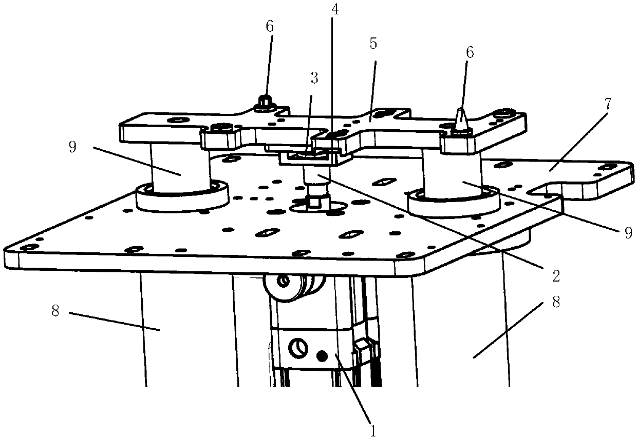
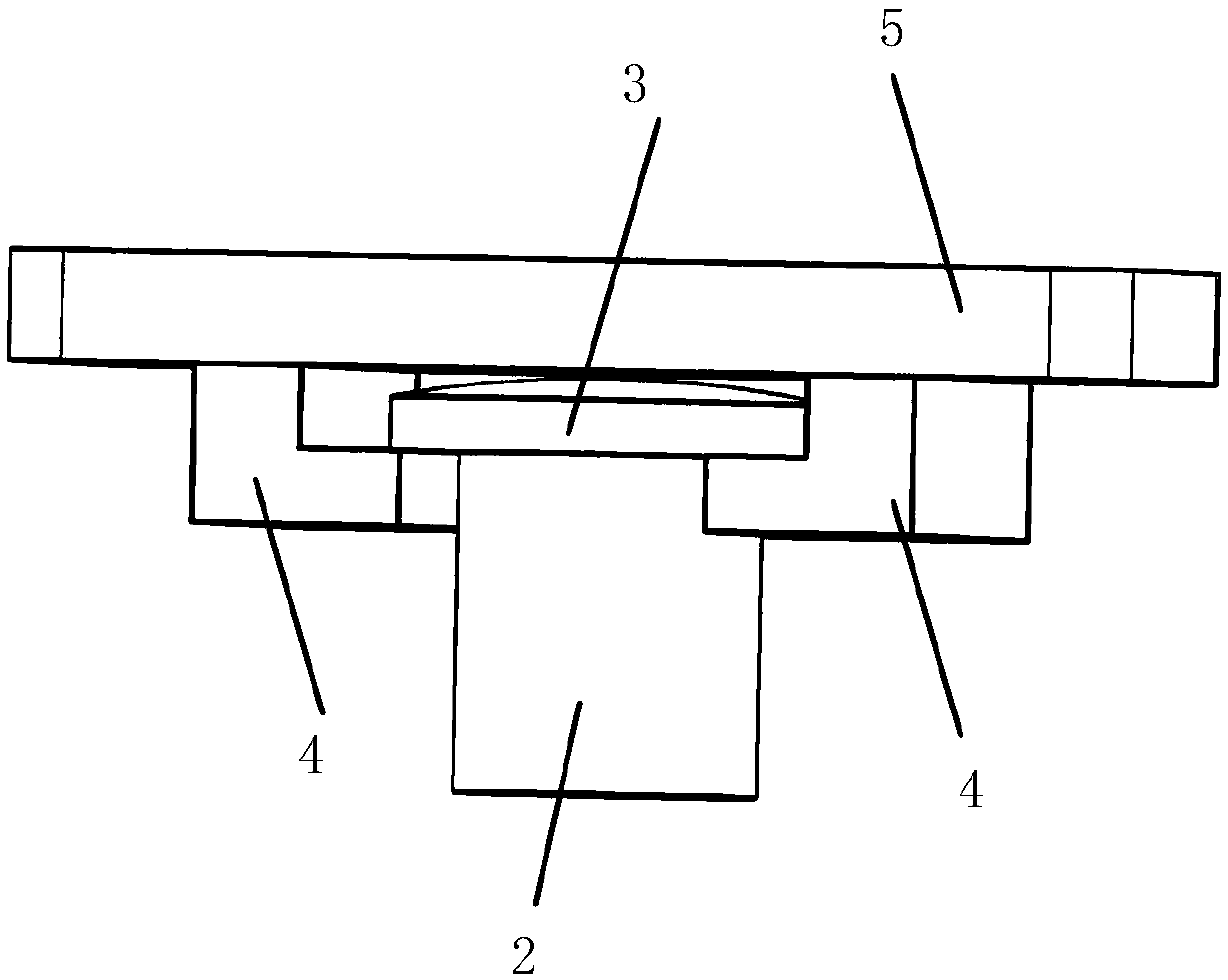
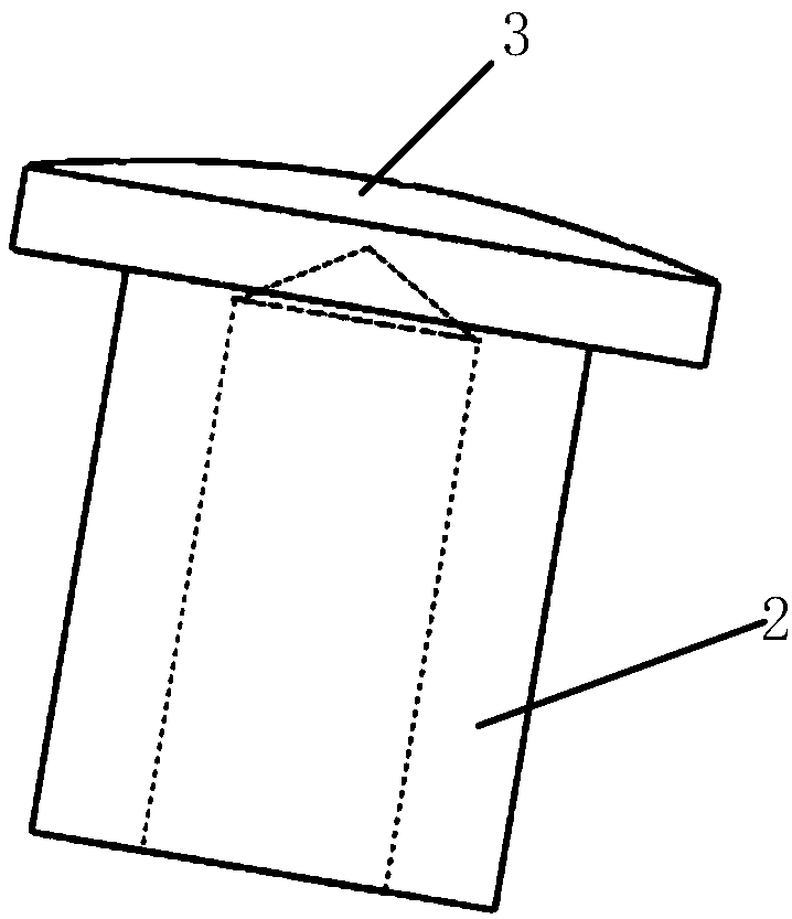
[0023] The following with attached Figure 1-3 A self-positioning tray mechanism of the present invention will be further described in detail.

[0024] A self-positioning tray mechanism of the present invention, please refer to Figure 1-3 , including a driving device, a connecting device, a tray 5 and at least two guiding devices, the connecting device is located between the driving device and the tray 5, the upper end surface of the connecting device is a spherical surface, and the upper end of the connecting device is spherical contact type Clamped on the lower part of the tray 5, the lower end of the connecting device is detachably fixed on the upper part of the driving device, the guiding device is movably connected to the left and right sides of the driving device up and down, and the upper end of the guiding device is connected to the upper part of the driving device. The lower end of the pallet 5 is fixedly connected, and the workpiece is releasably fixed on the palle...


PUM


Abstract

The invention discloses a self-positioning pallet mechanism. The mechanism comprises a driving device, a connecting device, a pallet and at least two guide devices. The connecting device is located between the driving device and the pallet, the upper end of the connecting device is a spherical surface, and the spherical surface at the upper end of the connecting device is clamped to the lower portion of the pallet in a contact mode. The lower end of the connecting device is detachably fixed to the upper portion of the driving device, the guide devices are vertically and movably connected to the left side and the right side of the driving device, the upper ends of the guide devices are fixedly connected with the lower end of the pallet, and workpieces are detachably fixed to the pallet. Theself-positioning pallet mechanism is simple in structure, convenient to machine, low in cost and reliable, the load of maintenance personnel and fault frequency and time of equipment can be effectively reduced, and the maintenance efficiency and the equipment operation stability are improved.

Description

technical field [0001] The invention relates to the technical field of pallet lifting, in particular to a self-positioning pallet mechanism. Background technique [0002] As a common equipment roller table lifting mechanism, the tooling pallet lifting mechanism is widely used in various non-standard customized equipment on the engine block and cylinder head line. The existing tooling pallet mechanism directly connects the cylinder and the pallet through threads, and relies on the cylinder and two guide rods to realize the vertical lifting of the pallet. The main defects of this structure are: in this structure, the threaded connection method requires high machining accuracy of each part. In this structure, the cylinder rod, guide rod and pallet are connected by threaded connection, and the adjustable range of each part is small. If the threaded hole is vertical If the accuracy is low, the guides at both ends of the tray and the cylinder rod will easily get stuck during use ...

Claims


Application Information

Patent Timeline
Patent Type & Authority Applications(China)
IPC IPC(8): B65G47/24
CPCB65G47/24
Inventor 王飞朱金辉冉光伟
Owner SAIC-GM-WULING AUTOMOBILE CO LTD
Why Eureka
Try Eureka