Drainer with heat recovery function

A technology of heat recovery and function, applied in water supply installations, indoor sanitary piping installations, buildings, etc., can solve problems such as impurity and dirt cleaning, and achieve the effects of eliminating air pollution, sufficient heat absorption, and high heat absorption efficiency

Pending Publication Date: 2020-07-03
张仁海
View PDF1 Cites 2 Cited by
  • Summary
  • Abstract
  • Description
  • Claims
  • Application Information

AI Technical Summary

Problems solved by technology

[0004] The present invention intends to provide a drainer with heat recovery function to solve the problem in the prior art that the impurities and dirt attached to the coil cannot be cleaned

Method used


Image

  • Drainer with heat recovery function

Examples


Embodiment 1

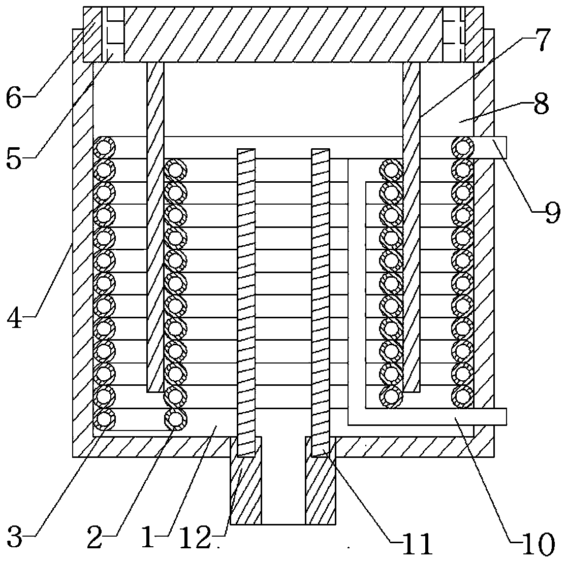
[0017] Embodiment 1: as figure 1 , a drainer with heat recovery function, comprising an outer cylinder 4, the top of the outer cylinder 4 is fastened with a cylinder cover 6, the cylinder cover 6 is coaxially welded with an isolation tube 7, and the isolation tube 7 separates the inner space of the outer cylinder 4 from the From the outside to the inside, it is divided into an outer water tank 8 and an inner water tank 1 in turn. The edge of the cylinder cover 6 is provided with an annular waste water inlet connected to the outer water tank 8. The waste water inlet is also welded with a filter screen 5. The outer water tank 8 is provided with a The first coil 3, the top of the right side of the first coil 3 is welded and communicated with the water inlet pipe 9, the inner tank 1 is provided with the second coil 2 communicating with the first coil 3, the right side of the second coil 2 The top is welded and communicated with a water outlet pipe 10 protruding out of the outer cy...

Embodiment 2

[0023] Embodiment 2: The difference between embodiment 2 and embodiment 1 is only that the drain pipe 11 is coaxially rotated and connected with a connecting pipe (not shown in the figure), the bottom of the drain pipe 11 is provided with a first drainage hole, and the connecting pipe is provided with a A second drain hole communicating with the first drain hole. When no waste water flows into the outer water tank 8 and the inner water tank 1 from the outside, the waste water in the outer water tank 8 and the inner water tank 1 is in a static state. In order to prevent impurities and dirt in the waste water from adhering to the outer cylinder 4 and the first coil 3 and the second coil pipe 2. Therefore, by rotating the connecting pipe, the second drain hole communicates with the first drain hole, and waste water is discharged into the sewage outlet 12 through the first drain hole and the second drain hole.


PUM


Abstract

The invention discloses a drainer with a heat recovery function, and belongs to the technical field of waste heat recovery devices. The drainer comprises an outer cylinder, wherein the top of the outer cylinder is buckled with a cylinder cover, the cylinder cover is coaxially connected with an isolation pipe, the isolation pipe sequentially divides the inner space of the outer cylinder from outside to inside into an outer water tank and an inner water tank, the cylinder cover is further provided with a water inlet communicating with the outer water tank, the outer water tank is provided with afirst coil pipe, the inner water tank is provided with a second coil pipe communicating with the first coil pipe end to end, the bottom of the outer cylinder is provided with a drain outlet communicating with the inner water tank, and the drain outlet is coaxially and detachably connected with a drain pipe extending into the inner water tank. By arranging the detachable cylinder cover and the drain pipe, the outer cylinder, the inner cylinder, the first coil pipe and the second coil pipe can be conveniently cleaned, and long-term cleaning and high-efficiency heat absorption efficiency can bemaintained.

Description

technical field [0001] The invention relates to the technical field of waste heat recovery devices, in particular to a drainer with heat recovery function. Background technique [0002] Waste heat refers to the sensible heat and latent heat that have not been rationally utilized in the original design in the energy-consuming devices of industrial enterprises that have been put into operation due to the limitations of factors such as history, technology, and concepts. Steam waste heat, high temperature products and slag waste heat, chemical reaction waste heat, combustible waste gas, waste liquid and waste heat, etc. [0003] With the improvement of people's living standards, hot water is used more and more widely, such as domestic hot water and industrial hot water, but the temperature of wastewater generated after hot water use is still high. If the wastewater is directly discharged into the sewer, it will inevitably It will cause waste of heat. For this reason, Chinese p...

Claims


Application Information

Patent Timeline
Patent Type & Authority Applications(China)
IPC IPC(8): E03C1/00E03C1/22E03C1/264
CPCE03C1/00E03C1/22E03C1/264E03C2001/005
Inventor 张仁海张昊宇
Owner 张仁海
Why Eureka
Try Eureka