

Concrete protective film laying device
A technology of laying device and protective film, applied in the direction of roads, road repair, roads, etc., can solve the problems of poor laying quality and slow laying of concrete protective film, and achieve the effect of improving construction quality, avoiding uneven laying problems and smooth conveying.
- Summary
- Abstract
- Description
- Claims
- Application Information
AI Technical Summary
Problems solved by technology
Method used
Image

Examples
Embodiment approach 1
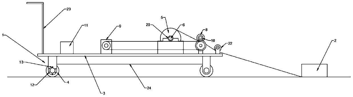
[0033] This embodiment, as the basic embodiment of the present invention, discloses a concrete protective film laying device, the specific structure is as follows figure 1 and Figure 4 As shown, it includes a laying trolley 1 and a fixed pile 2. The laying trolley 1 includes a frame 3, and the two sides of the bottom of the frame 3 are rotated to be provided with mutually matched rollers 4, and the rollers 4 are connected by rubber crawlers 24; The front section of the frame 1 is fixedly provided with a cart handrail 23, the middle part of the frame 1 is fixedly provided with a controller 11 and a servo motor 9 electrically connected to each other, the controller 11 adopts a PLC controller, and the tail portion of the frame 3 is provided with useful The rotating shaft 6 on which the film roll 5 is placed; the tail end of the frame 3 is also rotated to be provided with an active clamping discharge roller 7 and a driven clamping discharge roller 8, and the active clamping disch...
Embodiment approach 2
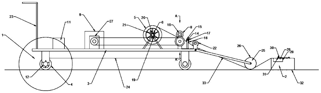
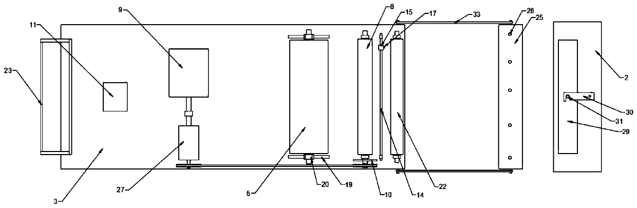
[0036] This embodiment, as a preferred embodiment of the present invention, discloses a concrete protective film laying device, the specific structure is as follows Figure 2 to Figure 5 As shown, it includes a laying trolley 1 and a fixed pile 2. The laying trolley 1 includes a frame 3. Two U-shaped support frames 19 that cooperate with each other are fixedly arranged on both sides of the frame 3 tail. A rotating shaft 6 is provided, and the middle part of the rotating shaft 6 is evenly provided with a plurality of support frames 21 adapted to the packaging tube of the film roll 5, and the two ends of the rotating shaft 6 are provided with rolling bearings 20 adapted to the U-shaped support frame 19, which are passed through the U-shaped The opening end bracket of the shaped support frame 19 is erected with a rotating shaft 6; meanwhile, the tail portion of the frame 3 is also rotated to be provided with an active clamping discharge roller 7 and a driven clamping discharge rol...
PUM
 Abstract
Description
Claims
Application Information