
Intelligent lock

A kind of lock, intelligent technology, applied in the direction of building locks, non-mechanical transmission-operated locks, buildings, etc., can solve the problem that affects the actual interests and experience of users, is difficult to meet the functional requirements of smart door locks, and cannot meet the high performance of smart door locks, etc. problems, to achieve the effect of low after-sales maintenance costs, saving after-sales maintenance costs, and improving user satisfaction

Inactive Publication Date: 2020-07-03
苏州九邦机电有限公司
View PDF6 Cites 9 Cited by
  • Summary
  • Abstract
  • Description
  • Claims
  • Application Information

AI Technical Summary

Problems solved by technology

[0002] In the prior art, in the field of smart door locks, traditional mechanical lock bodies are generally used, or simply electronic lock bodies with motor clutch mechanisms are used, which is difficult to meet people's functional requirements for smart door locks.
[0003] As the core component of the door lock, the performance of the lock body is directly related to the overall performance of the door lock, which in turn affects the actual interests and user experience of the user. The traditional mechanical lock body and electronic clutch lock body obviously cannot meet the requirements The high-performance requirements of smart door locks, and the high failure rate caused by its low reliability have been criticized by the market. Not only the production cost is not low, but also the high after-sales maintenance cost has made many manufacturers and users tremble.

Method used


Image

  • Intelligent lock
  • Intelligent lock
  • Intelligent lock

Examples


Embodiment Construction

[0024] The technical solution of a smart lock provided by the specific embodiment of the present invention will be clearly and completely described below in conjunction with the accompanying drawings in the specific embodiment of the present invention. Obviously, the described embodiment is only a part of the embodiment of the present invention. rather than all examples. Based on the specific embodiments of the present invention, all other embodiments obtained by persons of ordinary skill in the art without any creative efforts fall within the protection scope of the present invention.

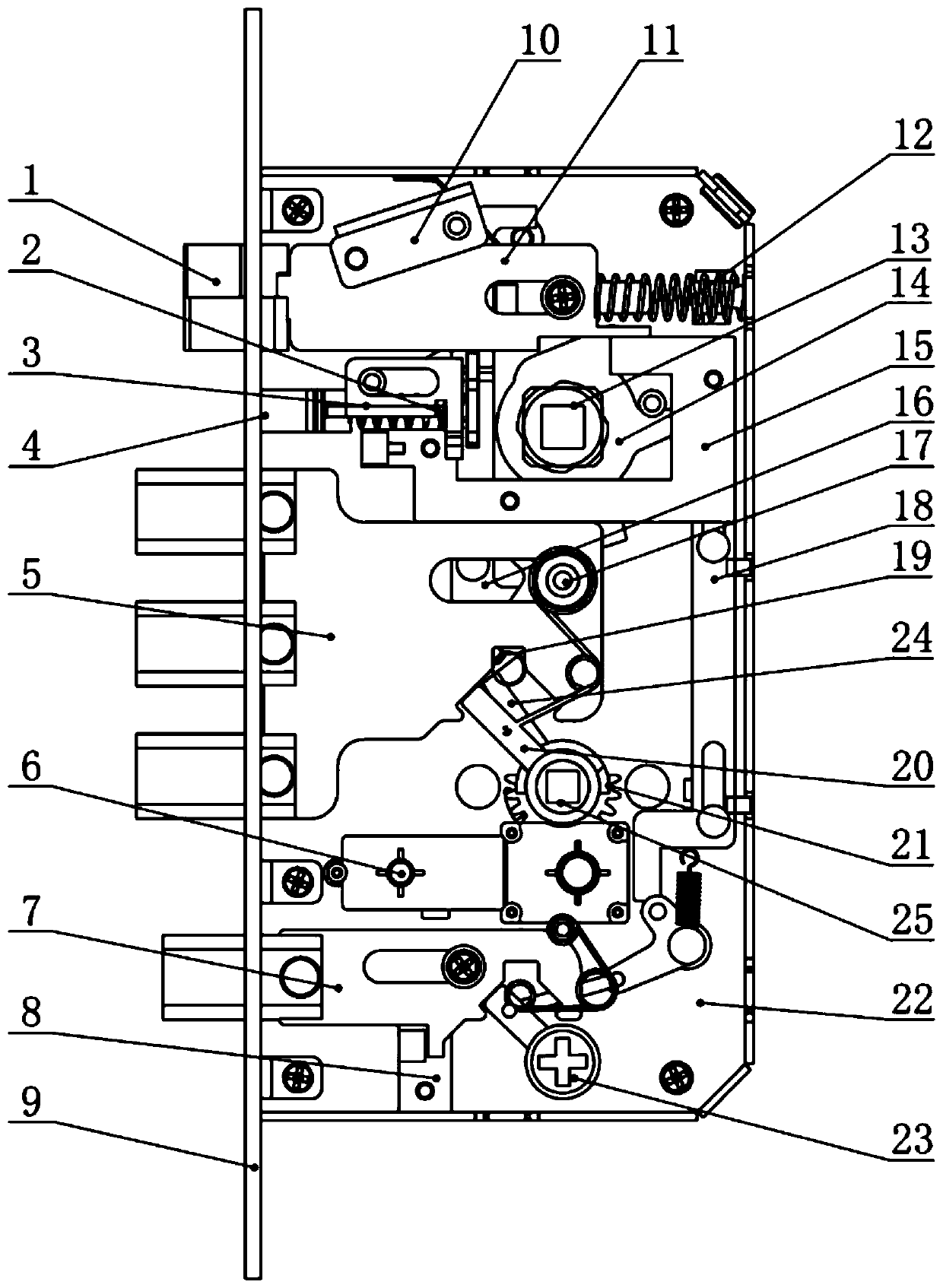
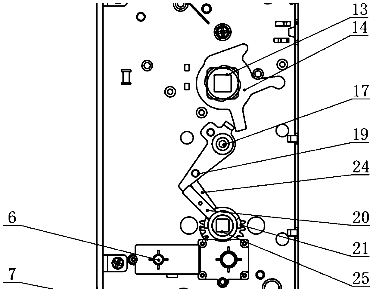
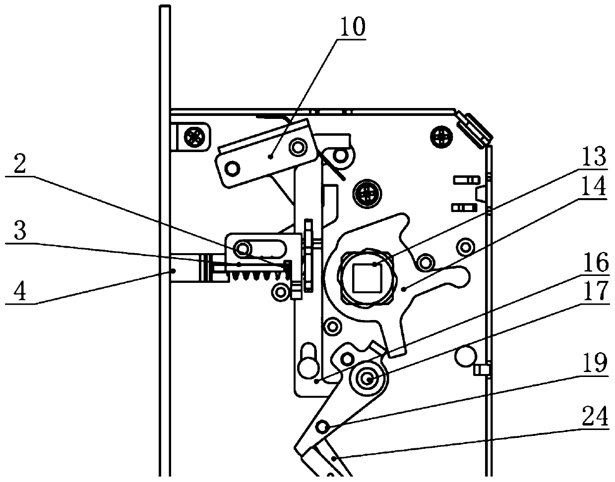
[0025] A kind of intelligent lock provided in this embodiment, the specific internal structure installation schematic diagram is as follows figure 1 As shown, it includes a lock case 22, a deadbolt and a deadbolt driving mechanism. The lock case 22 is provided with various mounting parts and external interfaces, and a deadbolt hole for the deadbolt to pass through. The deadbolt drives A mecha...


PUM


Abstract

The invention provides an intelligent lock which comprises a lock shell, a spring bolt and a spring bolt driving mechanism. The spring bolt comprises a main spring bolt assembly, a touch bolt assembly and an inclined bolt assembly, the main spring bolt assembly comprises a main spring bolt, the touch bolt assembly comprises a touch bolt supporting plate, a touch bolt spring and a touch bolt, andthe touch bolt can be automatically ejected out under the action of the touch bolt spring; the spring bolt driving mechanism comprises a shifting wheel, a shifting fork, a square shaft shifting piecewhich are sequentially connected and further comprises a driving motor and a rotating handle, the main spring bolt is controlled by the shifting wheel to stretch out and draw back, and the shifting wheel can be driven by a motor, a square shaft shifting piece or a key; a safety bolt assembly can be driven to be locked through a mechanical manual knob, unlocking cannot be achieved outside a door, and locking of all the spring bolts can be mechanically relieved in one step inside the door through a handle rotating shaft; and through the combination of automatic unlocking and mechanical unlocking, automatic unlocking can be achieved through fingerprints, face recognition, cards and the like, unlocking and locking can also be achieved in the mode that the shifting wheel is driven by the key and the square shaft shifting piece is driven by the handle, the requirement of the high-performance intelligent door lock is better met, and the reliability of the lock is improved.

Description

technical field [0001] The invention relates to the technical field of intelligent door locks, in particular to an intelligent lock. Background technique [0002] In the prior art, in the field of smart door locks, traditional mechanical lock bodies are generally used, or simply electronic lock bodies with motor clutch mechanisms are used, which is difficult to meet people's functional requirements for smart door locks. [0003] As the core component of the door lock, the performance of the lock body is directly related to the overall performance of the door lock, which in turn affects the user's actual interests and user experience. The traditional mechanical lock body and electronic clutch lock body obviously cannot meet the requirements The high performance requirements of smart door locks, and the high failure rate brought about by its low reliability have been criticized by the market. Not only the production cost is not low, but also the high after-sales maintenance co...

Claims


Application Information

Patent Timeline
Patent Type & Authority Applications(China)
IPC IPC(8): E05B63/14E05B47/00E05B63/00E05B15/00
CPCE05B15/00E05B47/0001E05B47/0012E05B63/0065E05B63/146E05B2047/0069
Inventor 闵朝辉杨勇
Owner 苏州九邦机电有限公司
Learn More