Fault Tolerant Reversing Valve

A technology for reversing valves and spools, applied in the field of reversing valves, can solve problems such as high manufacturing requirements, inability to continue working, and unsatisfactory performance, and achieve the effects of reducing the number of parts to be processed, realizing real-time detection, and simplifying the structure of the rotary valve

Inactive Publication Date: 2021-09-03
NINGBO INST OF TECH ZHEJIANG UNIV ZHEJIANG
View PDF0 Cites 0 Cited by
  • Summary
  • Abstract
  • Description
  • Claims
  • Application Information

AI Technical Summary

Problems solved by technology

[0005] 1. The existing electro-hydraulic reversing technology does not have fault-tolerant characteristics. For the servo valve, when the driving part that drives the axial movement of the valve core fails, it cannot continue to work; for the existing rotary valve, when the driving part that controls the rotation of the valve core After some failures, they cannot continue to work, so they cannot meet the requirements of some electro-hydraulic commutation systems that are inconvenient to replace driving components.
[0006] 2. The existing rotary valve reversing technology generally adopts the matching design of the valve core and valve sleeve, the structure is relatively complicated, and the manufacturing requirements are high, thus limiting its wide application
[0007] 3. The existing rotary valve reversing technology cannot effectively realize the detection of the valve core position
In the absence of a spool position detection method, on the one hand, it is impossible to determine the zero position of the spool; on the other hand, in practical applications, it cannot meet certain occasions that require precise control of the reversing position.

Method used


Image

  • Fault Tolerant Reversing Valve
  • Fault Tolerant Reversing Valve
  • Fault Tolerant Reversing Valve

Examples


Embodiment Construction

[0041] The following will clearly and completely describe the technical solutions in the embodiments of the present invention with reference to the accompanying drawings in the embodiments of the present invention. Obviously, the described embodiments are some of the embodiments of the present invention, but not all of them. Based on the embodiments of the present invention, all other embodiments obtained by persons of ordinary skill in the art without making creative efforts belong to the protection scope of the present invention.

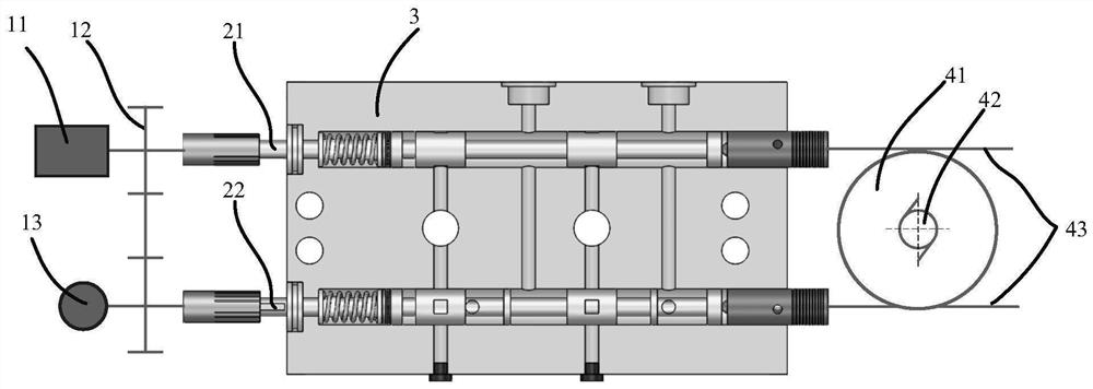
[0042] refer to figure 1 -, the present invention discloses a fault-tolerant reversing valve, which includes a circumferential driving mechanism, a main valve (including a valve body 3 and a valve core part), and an axial driving mechanism. Wherein, the circumferential driving mechanism includes a first servo motor 11, a gear transmission mechanism 12 (comprising a first gear, a fourth gear, and a second gear meshed in sequence) and a hand wheel 1...


PUM


Abstract

The invention discloses a fault-tolerant reversing valve, which comprises a main body valve, a circumferential driving mechanism and an axial driving mechanism. One end of the main body valve is connected to the circumferential driving mechanism, and the other end is connected to the axial driving mechanism. The main body valve is provided with a first spool and a second spool. One end of the first spool is connected to the first servo motor through the first gear, and the other end is against the first linear slider. The first linear slider is connected to the The first rack; one end of the second spool is connected to the hand wheel through the second gear, and the other end is against the second linear slider, and the second slider is connected to the second rack; both the first gear and the second gear are connected to the second gear. The fourth gear is meshed, the first rack and the second rack are meshed with the third gear, and the second servo motor is connected to the third gear. The fault-tolerant reversing valve adopts the method of direct cooperation between the valve body and the valve core, omitting the valve sleeve structure, and after the main drive motor is damaged, it can continue to perform oil reversing through other driving parts.

Description

technical field [0001] The invention belongs to the field of reversing valves, in particular to a fault-tolerant reversing valve. Background technique [0002] The fault-tolerant control of electro-hydraulic commutation technology refers to controlling the hydraulic actuators to continue to complete the commutation function by relying on the driving components that can still work normally after some driving components fail. Among them, the reversing valve is the core component of the electro-hydraulic reversing technology, and its performance and fault-tolerant control function directly determine the working performance and fault-tolerant performance of the electro-hydraulic reversing technology. [0003] So far, there is no electro-hydraulic directional valve with fault-tolerant function, that is, after the drive part fails, the electro-hydraulic directional valve cannot continue to work. In the absence of fault-tolerant function, for some large-scale equipment that is inc...

Claims


Application Information

Patent Timeline
Patent Type & Authority Patents(China)
IPC IPC(8): F15B13/02F16K31/04F16K31/54
CPCF15B13/02F16K31/04F16K31/54
Inventor 刘毅陈德馨徐巧宁徐文凯韩冬
Owner NINGBO INST OF TECH ZHEJIANG UNIV ZHEJIANG
Why Eureka
Try Eureka