Device for detecting and adjusting gaps on two sides of rotating body in closed or semi-closed cavity

A technology of adjusting device and rotating body, applied in mechanical clearance measurement, transmission parts, belt/chain/gear, etc., can solve the problems of reducing mechanical efficiency, high cost, leakage, etc. Gap removal effect

Pending Publication Date: 2020-07-03
随州亿丰泵业有限公司
View PDF0 Cites 1 Cited by
  • Summary
  • Abstract
  • Description
  • Claims
  • Application Information

AI Technical Summary

Problems solved by technology

[0002] In the field of machinery, the use of a rotating body in a closed or semi-closed cavity is a very common structure, which requires precise axial positioning to ensure mechanical efficiency. If the gap between the two sides is too small, friction will occur, and if the gap is too large, it will The two sides are not sealed, resulting in leakage, and the gap on both sides is uneven, which will cause one side to rub and one side to leak, and the ideal mechanical efficiency cannot be achieved; in actual use, too many intermediate connectors make it difficult to distribute the precision of the size chain , the processing accuracy of each component is very high, and even cannot be guaranteed; and the rotating body is set in the box, and the actual assembly gap cannot be detected; the cost is too high or it cannot be realized, so the standard can only be lowered and the production can be downgraded, thereby reducing the mechanical efficiency and causing waste

Method used


Image

  • Device for detecting and adjusting gaps on two sides of rotating body in closed or semi-closed cavity
  • Device for detecting and adjusting gaps on two sides of rotating body in closed or semi-closed cavity

Examples


Embodiment Construction

[0029] The principles and features of the present invention are described below in conjunction with the accompanying drawings, and the examples given are only used to explain the present invention, and are not intended to limit the scope of the present invention.

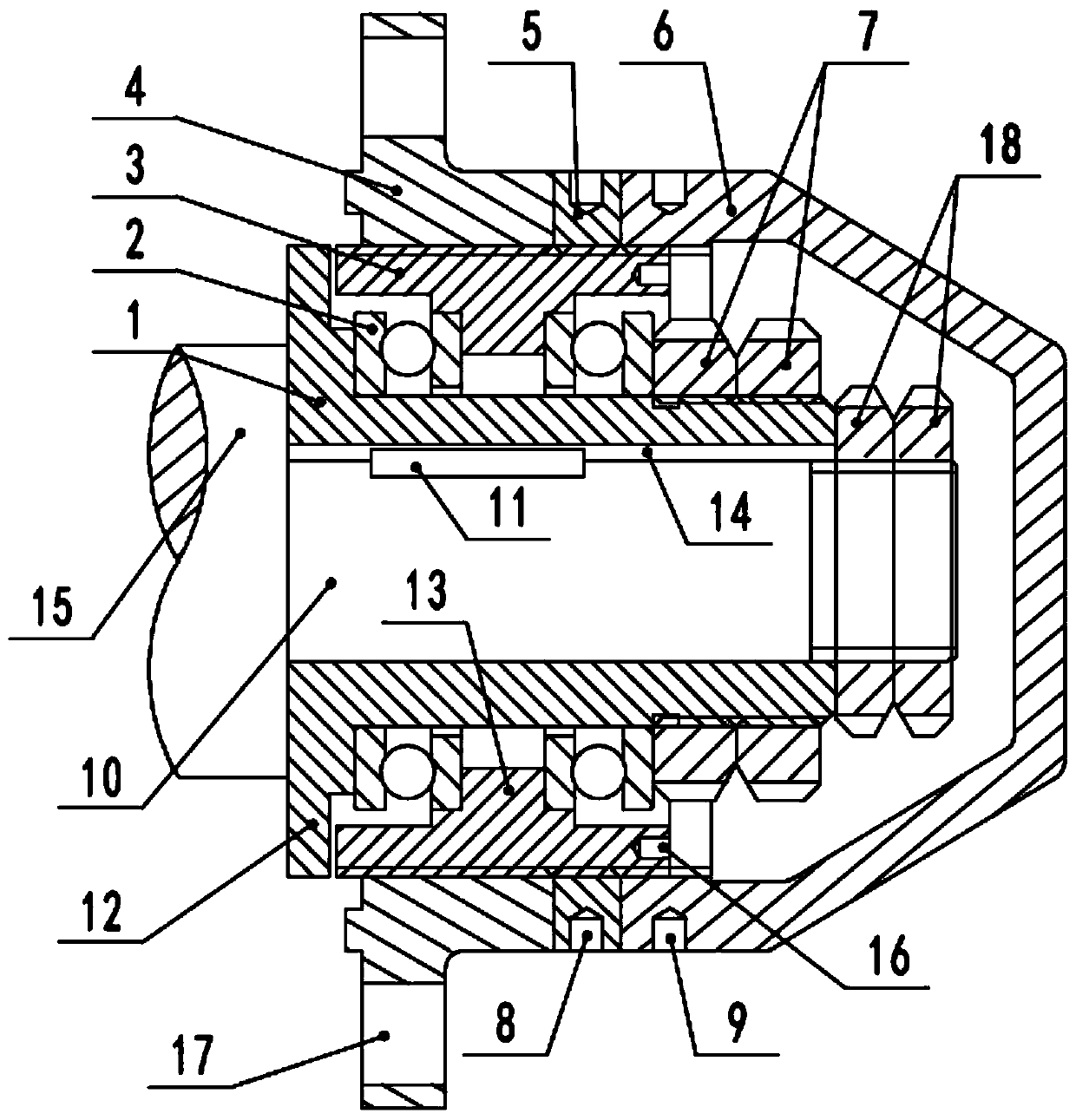
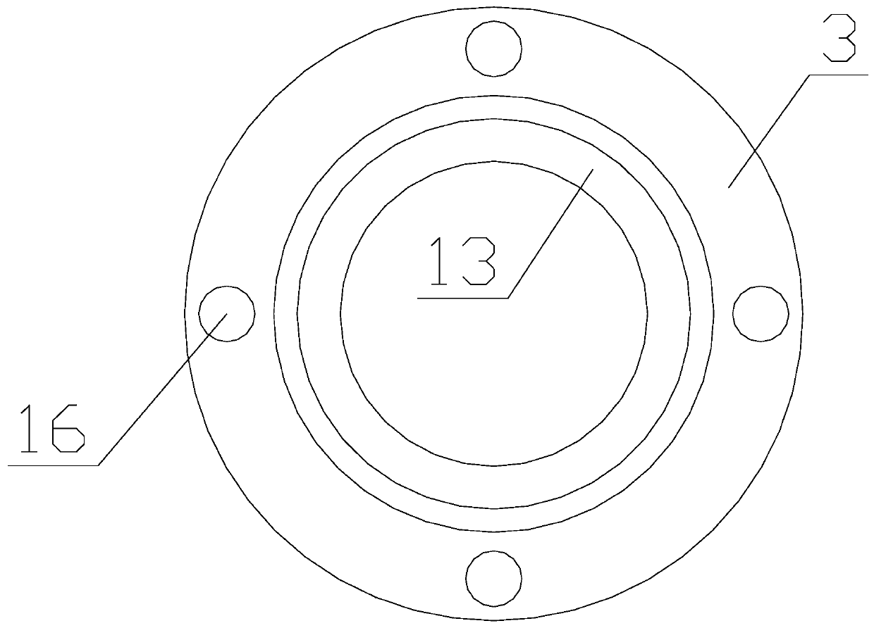
[0030] Such as figure 1 and 2 As shown, the gap detection and adjustment device on both sides of the rotating body in a closed or semi-closed cavity includes a connecting sleeve 1, a bearing 2, an adjusting seat 3 and a connecting seat 4, and the connecting sleeve 1 is coaxially set on the rotating body. One end of the body shaft 10, the connecting shaft sleeve 1 can follow the rotating body shaft 10 to rotate around the central axis of the rotating body shaft 10, the bearing 2 is sleeved on the outer periphery of the connecting shaft sleeve 1, the connecting The seat 4 is fixedly connected to the box for placing the rotating body shaft 10, the connecting seat 4 and the adjusting seat 3 are ring-shaped, and the adj...


PUM


Abstract

The invention relates to a device for detecting and adjusting gaps on two sides of a rotating body in a closed or semi-closed cavity. The device comprises a connecting shaft sleeve, bearings, an adjusting seat, an adjusting locking nut, a protective cover, bearing limiting nuts and a connecting seat, wherein the connecting shaft sleeve is connected with the adjusting seat through the bearings, theconnecting shaft sleeve can freely rotate relative to the adjusting seat and is axially of an integral linkage structure, an inner hole of the connecting seats is in threaded transmission connectionwith an outer circle of the adjusting seat, and the adjusting seat is provided with a locking device and a sealing protection device; the connecting seat is arranged on the side cover of an outer cover of a rotating body, the connecting shaft sleeve is connected with a shaft head at one end of the rotating body, and the adjusting seat is rotated to drive the rotating body to move in the axial direction so as to achieve the effects of adjusting and detecting; and scale values are arranged on the connecting seat, and the accurate position of adjustment is displayed. The device has the beneficialeffects that during adjustment, the axial gaps are eliminated, the positioning of the rotating body can be accurately adjusted, and the actual side distance can be detected.

Description

technical field [0001] The invention relates to a shafting component, in particular to a device for detecting and adjusting the gap between two sides of a rotating body in a closed or semi-closed cavity. Background technique [0002] In the field of machinery, the use of a rotating body in a closed or semi-closed cavity is a very common structure, which requires precise axial positioning to ensure mechanical efficiency. If the gap between the two sides is too small, friction will occur, and if the gap is too large, it will The two sides are not sealed, resulting in leakage, and the gap on both sides is uneven, which will cause one side to rub and one side to leak, and the ideal mechanical efficiency cannot be achieved; in actual use, too many intermediate connectors make it difficult to distribute the precision of the size chain , the processing accuracy of each component is very high, and even cannot be guaranteed; and the rotating body is set in the box, and the actual ass...

Claims


Application Information

Patent Timeline
IPC IPC(8): F16H57/022F16H57/04F16H57/029G01B5/14
CPCF16H57/022F16H57/029F16H57/04F16H2057/0221G01B5/14
Inventor 李安义
Owner 随州亿丰泵业有限公司
Why Eureka
Try Eureka