Descaling device using water kinetic energy
A technology of water kinetic energy and cleaning device, which is applied in the field of boilers, can solve problems such as inability to realize real-time descaling, and achieve the effect of simple installation and easy maintenance and replacement
- Summary
- Abstract
- Description
- Claims
- Application Information
AI Technical Summary
Problems solved by technology
Method used
Image

Examples
Embodiment 1
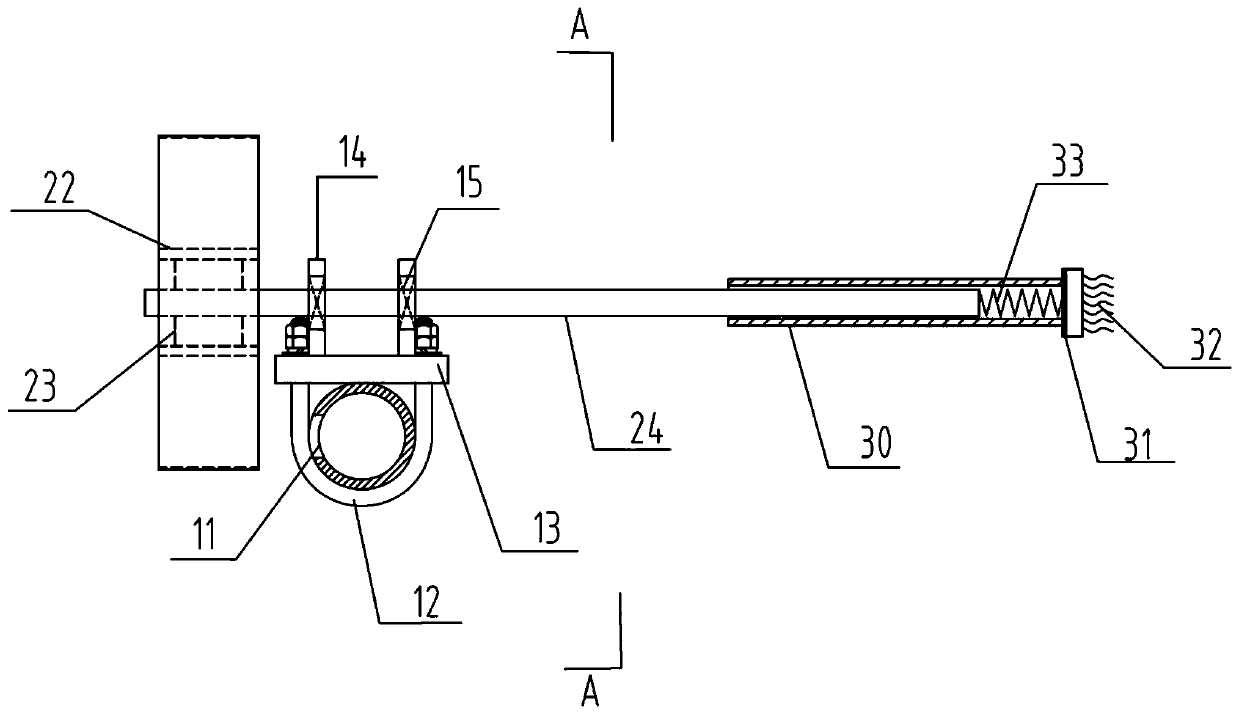
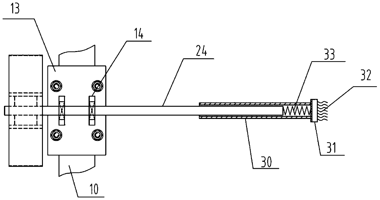
[0028] like Figure 1-4 As shown, the descaling device using hydrokinetic energy includes a water supply pipe, a turbine device and a cleaning device. The turbine device is installed on the water supply pipe, and the cleaning device is installed on the turbine device. The cleaning device is located in the water space in the boiler, where it is prone to scale, and is used to remove the scale in the boiler. The water supply pipe is the original boiler and is used to add water to the boiler. The water supply pipe is provided with a plurality of small water spray holes for spraying the water in the water supply pipe.
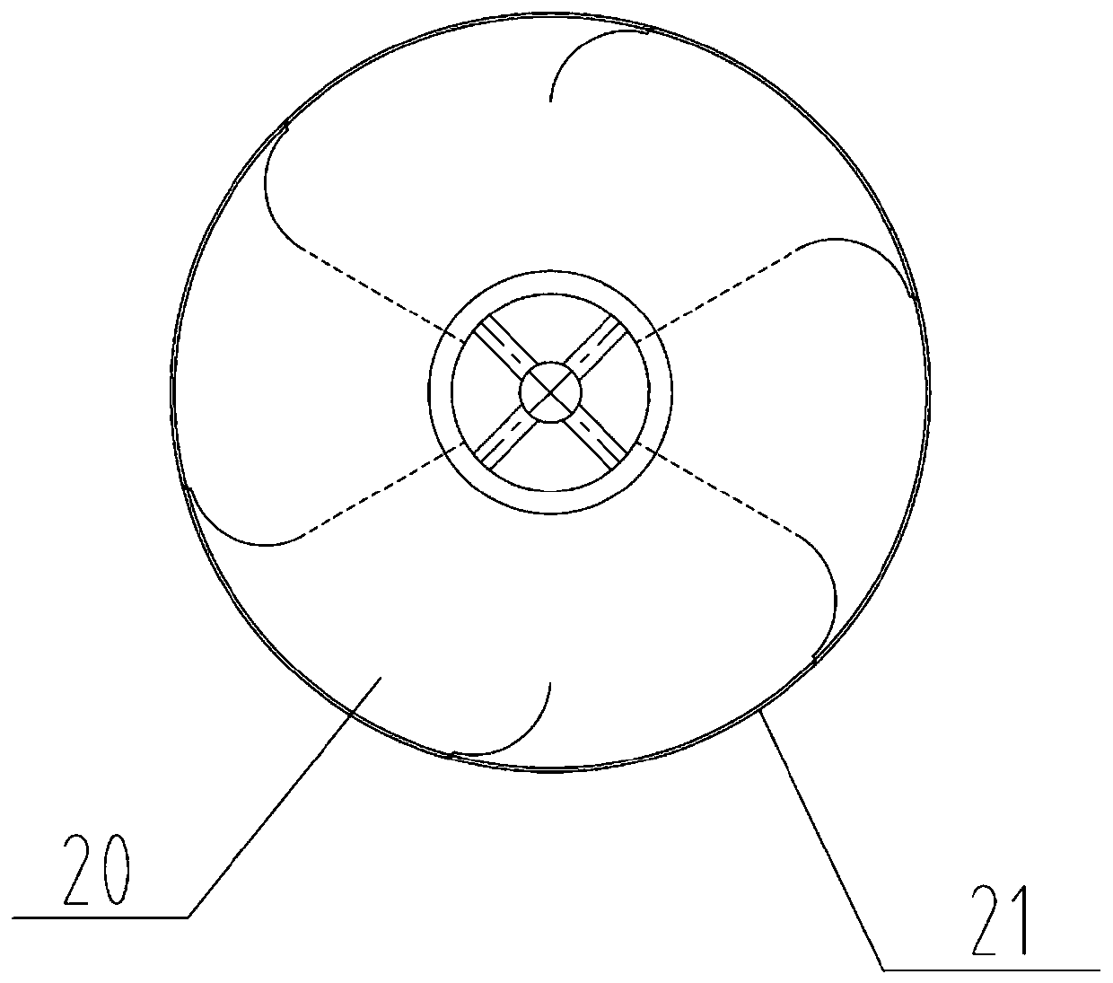
[0029] like figure 1 , 3 As shown, the turbine device includes turbine blades and a drive shaft. The turbine blades are defined by inner and outer rings, and the blades are in the shape of curved blades. The water sprayed from the small water spray hole of the water supply pipe can drive the turbine blades to rotate. Four top plates are arranged on the inner ...
Embodiment 2
[0032] like Figure 5-6 As shown, the descaling device of this embodiment includes a water supply pipe, a turbine device and a cleaning device. The turbine device is installed on the water supply pipe, and the cleaning device is installed on the turbine device. The turbine device in this embodiment includes turbine blades, a transmission shaft and a driven shaft. The turbine blades are straight blades, one end of the transmission shaft is connected with the turbine blades, and the other end is equipped with gears. A gear is installed at one end of the driven shaft, and the gear is vertically driven with the gear on the transmission shaft. The other end of the driven shaft is equipped with a cleaning device. The cleaning device in this embodiment is the same as that in Embodiment 1, and will not be repeated here. In order to ensure the stable installation of the turbine device on the water supply pipe, a pair of U-shaped bolts are set on the water supply pipe, and a bottom p...
Embodiment 3
[0035] like Figure 7-8 As shown, the descaling device of this embodiment includes a water supply pipe, a turbine device and a cleaning device. The turbine device includes turbine blades, a drive shaft and a driven shaft. The turbine blades are installed inside the water supply pipe, and the blades are straight blades. In order to install the turbine blades into the water supply pipe, it is necessary to modify the original water supply pipe of the boiler to form a cavity capable of accommodating the turbine blades. When water enters the water supply pipe, the water flow directly washes the turbine blades and drives the turbine blades to rotate. The transmission shaft passes through the water supply pipe and is connected with the first bearing arranged on the pipe wall of the water supply pipe. The transmission shaft is vertically connected with the driven shaft and driven by gears. Two third bearing plates are welded on the wall surface of the outer pipe of the water suppl...
PUM
 Abstract
Description
Claims
Application Information
 - R&D
- Intellectual Property
- Life Sciences
- Materials
- Tech Scout
- Unparalleled Data Quality
- Higher Quality Content
- 60% Fewer Hallucinations
Browse by: Latest US Patents, China's latest patents, Technical Efficacy Thesaurus, Application Domain, Technology Topic, Popular Technical Reports.
© 2025 PatSnap. All rights reserved.Legal|Privacy policy|Modern Slavery Act Transparency Statement|Sitemap|About US| Contact US: help@patsnap.com