
Cold-heat source system flow testing device

A system flow and testing device technology, applied in measuring devices, measuring heat, and detecting fluid flow with electromagnetic flowmeters, etc., can solve the problems that flow monitoring and related analysis are not perfect and accurate, and it is difficult to meet the stability of the production process, etc., to achieve Low price, reduce manpower consumption, and realize the effect of long-distance concentration

Pending Publication Date: 2020-07-03
SHENYANG JIANZHU UNIVERSITY
View PDF0 Cites 0 Cited by
  • Summary
  • Abstract
  • Description
  • Claims
  • Application Information

AI Technical Summary

Problems solved by technology

In the process of formulating energy-saving strategies and improving energy utilization, temperature, pressure and flow are the main influencing factors. Among them, the detection and consideration of temperature and pressure are very mature, but the monitoring and related analysis of flow are not perfect and accurate enough. Therefore, the importance of flow monitoring is even more prominent
In general, the flow monitoring will be measured directly or on the outer wall of the pipeline, such as electromagnetic flowmeters and ultrasonic flowmeters, which are difficult to meet the stability of the production process, as well as high precision, low error, strong real-time performance, and the ability to achieve Remote concentration requirements

Method used


Image

  • Cold-heat source system flow testing device
  • Cold-heat source system flow testing device
  • Cold-heat source system flow testing device

Examples


Embodiment Construction

[0020] The present invention will be further described below in conjunction with the accompanying drawings.

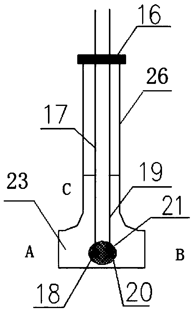
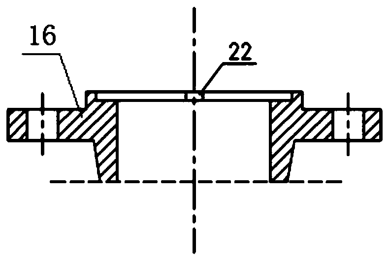
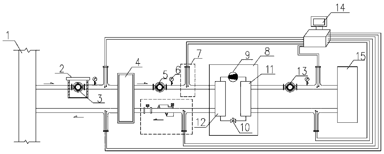
[0021] Such as figure 1 and figure 2 As shown, the flow test device of the cold and heat source system of the present invention includes a tee 23, the A port of the tee 23 is used as the water inlet, the B port is used as the water outlet, and the A port and the B port are on a straight line. The C port of 23 is connected with a test tube. One mouth of the test tube 26 is connected to the C port of the tee 23 , and the other mouth is sealed with a flange 16 , and the flange 16 is reserved with an opening 22 for a sensing line.

[0022] The tee 23 is provided with a net pocket 21, and the net pocket 21 is provided with a temperature probe 18 and a flow sensor 20, and the temperature probe 18 and the flow sensor 20 are connected to the data acquisition module through the sensing line A17, the sensing line B19 and the data acquisition module respectively. Connect, the...


PUM

PropertyMeasurementUnit
bearing capacityaaaaaaaaaa

Abstract

The invention discloses a cold-heat source system flow testing device, which comprises a tee joint, wherein a port A of the tee joint is used as a water inlet, a port B of the tee joint serves as a water outlet, a port C of the tee joint is connected with a test tube, a tube opening of the test tube is sealed through a flange, a net bag is arranged in the tee joint, the net bag is internally provided with a temperature probe and a flow sensor, and the temperature probe and the flow sensor are connected with a data acquisition module through a sensing line A and a sensing line B respectively. According to the invention, the temperature probe and the flow sensor are directly communicated with a water supply and return pipeline through the sensing lines, thereby realizing direct contact between the probe and a medium, and measuring the water supply and return temperature and flow of the ground source side and the user side.

Description

technical field [0001] The invention relates to a flow test device, more specifically, to a flow test device for a cold and heat source system. Background technique [0002] With the increasing development of industrial technology and the development and utilization of new energy, flow detection has become an important part of detection technology in the process of building energy-saving renovation. The flow can directly reflect the flow characteristics, working status and energy consumption of buildings. In the process of formulating energy-saving strategies and improving energy utilization, temperature, pressure and flow are the main influencing factors. Among them, the detection and consideration of temperature and pressure are very mature, but the monitoring and related analysis of flow are not perfect and accurate enough. Therefore, the importance of flow monitoring is even more prominent. In general, the flow monitoring will be measured directly or on the outer wall o...

Claims


Application Information

Patent Timeline
Patent Type & Authority Applications(China)
IPC IPC(8): G01F1/58G01F1/66G01K7/02
CPCG01F1/58G01F1/66G01K7/02
Inventor 刘馨桑婧萌梁传志冯国会赵赫李画
Owner SHENYANG JIANZHU UNIVERSITY
Learn More