
Textile fabric sampling device utilizing lever principle

A technology of textile fabrics and sampling devices, applied in the field of textile fabrics, can solve problems such as reduced service life of blades, irregular incisions, and inaccurate detection of fabrics, and achieve the effects of saving use costs, increasing service life, and reducing operational difficulty

Inactive Publication Date: 2020-07-03
吴茂根
View PDF0 Cites 1 Cited by
  • Summary
  • Abstract
  • Description
  • Claims
  • Application Information

AI Technical Summary

Problems solved by technology

[0003] However, the existing textile fabric sampling devices usually sample by cutting the fabric by hand pressure. Due to the pure pressure cutting, the physical strength of the sampling personnel is relatively high, and the operation is very laborious. Moreover, the incision is easy to be irregular due to inaccurate pressure control. , resulting in errors in the area of ​​the sampled cloth, resulting in inaccurate detection of the cloth. In addition, the cloth is cut off by pressing the blade, which has high requirements on the blade and causes great damage to the blade, resulting in a decrease in the service life of the blade and an increase in sampling costs. Moreover, due to The blade is often fixedly connected inside the sampling device, and the sampling device is usually hinged with connecting rods, which is troublesome to disassemble, which makes it difficult to replace the blade and wastes work efficiency

Method used


Image

  • Textile fabric sampling device utilizing lever principle
  • Textile fabric sampling device utilizing lever principle
  • Textile fabric sampling device utilizing lever principle

Examples


Embodiment Construction

[0026] The following will clearly and completely describe the technical solutions in the embodiments of the present invention with reference to the accompanying drawings in the embodiments of the present invention. Obviously, the described embodiments are only some, not all, embodiments of the present invention. Based on the embodiments of the present invention, all other embodiments obtained by persons of ordinary skill in the art without making creative efforts belong to the protection scope of the present invention.

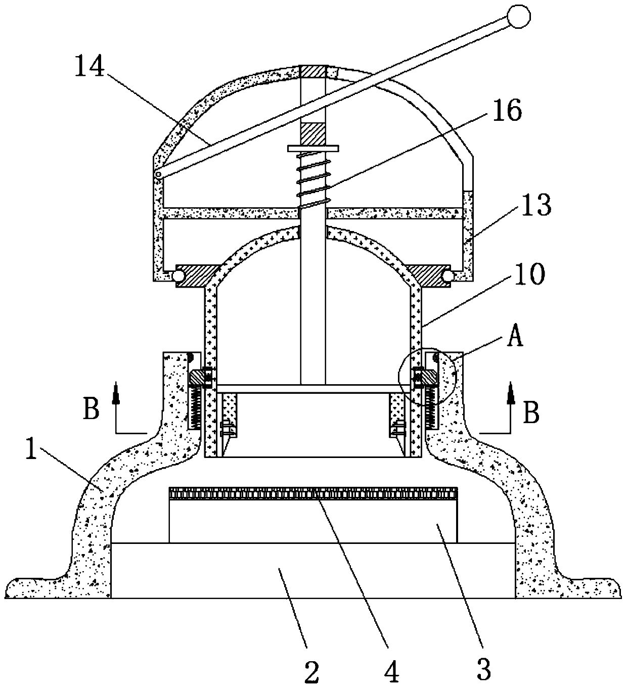
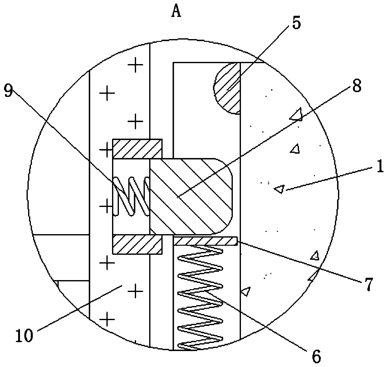
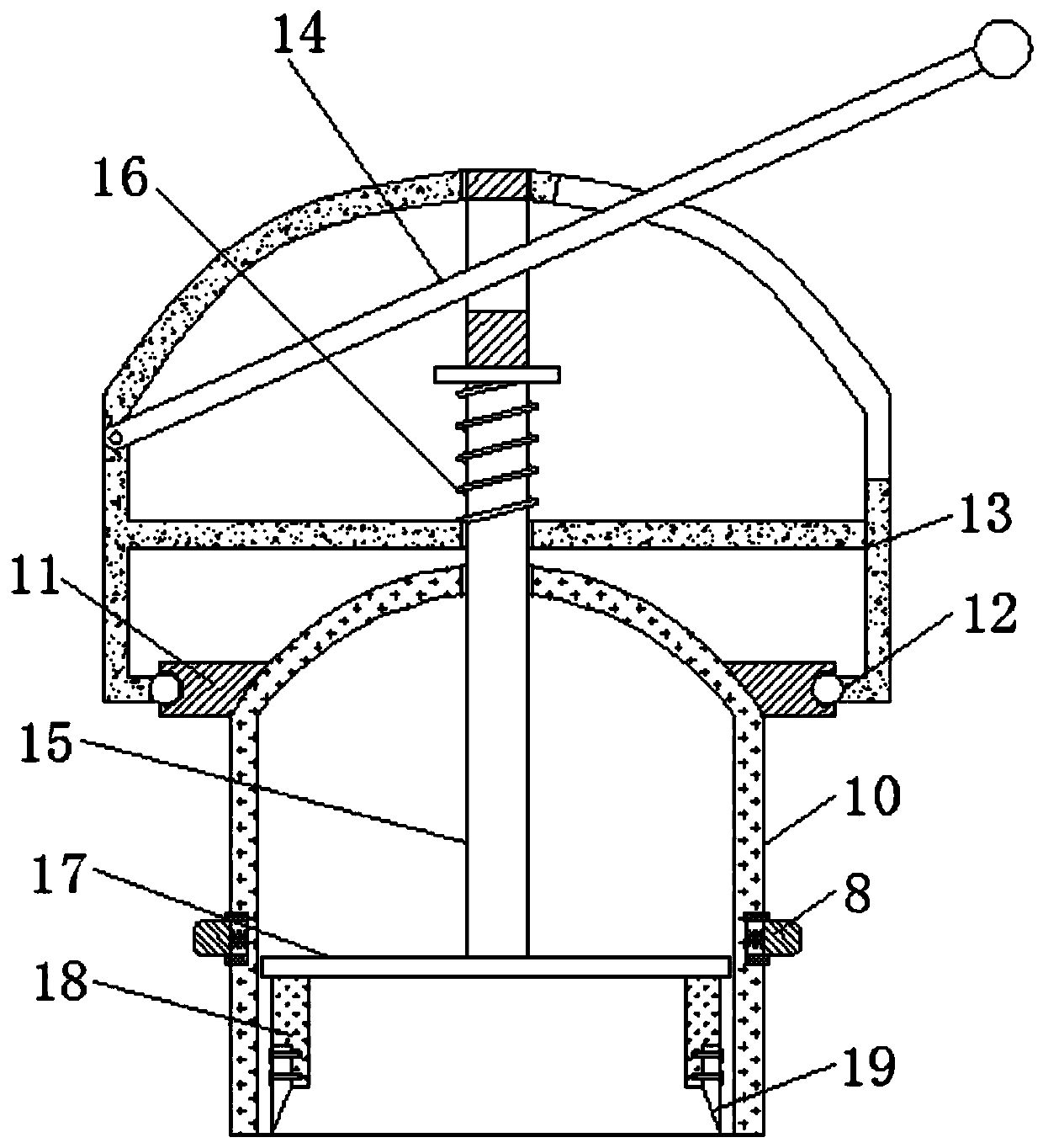
[0027] see Figure 1-4 , a textile fabric sampling device utilizing the principle of leverage, comprising a support frame 1, a base 2, a weighing body 3, a gasket 4, a stopper 5, a support spring 6, a support plate 7, a limit slider 8, and a limit spring 9 , housing 10, rotating chute 11, rotating slide block 12, turret 13, depression bar 14, connecting rod 15, compression spring 16, pressing plate 17, knife rest 18, blade 19, observation port 20.

[0028] Th...


PUM


Abstract

The invention relates to the technical field of textile fabrics, and further discloses a textile fabric sampling device utilizing a lever principle. The device comprises a supporting frame. A base isfixedly connected to the interior of the supporting frame. The top of the base is fixedly connected with a scale body. The top of the scale body is fixedly connected with a gasket. A stop block is fixedly connected to the interior of the supporting frame. A supporting spring is movably connected to the interior of the supporting frame. A supporting plate is fixedly connected to the tops of the supporting springs. The top of the supporting plate is movably connected with a limiting sliding block. A limiting spring is fixedly connected to the outer part of the limiting sliding block. The outer part of limiting sliding block is movably connected with a shell. With the use of the scale body and the gasket, the sample can be conveniently and directly weighed by the scale body after the samplingis completed so as to reduce the operation process and improve the efficiency, and the gasket provides effects of scale body protection, blade protection, blade loss reduction, blade service life prolonging and use cost saving.

Description

technical field [0001] The invention relates to the technical field of textile fabrics, in particular to a textile fabric sampling device utilizing the principle of leverage. Background technique [0002] Textile fabrics are divided into weft-knitted fabrics and warp-knitted fabrics according to weaving methods. Weft-knitted fabrics are often made of low-elastic polyester yarns or special-shaped polyester yarns, nylon yarns, cotton yarns, wool yarns, etc., and are made of flat stitches. , changing flat stitch, ribbed flat stitch, double rib plain stitch, jacquard stitch, terry stitch, etc., are woven on various weft knitting machines. When the textile fabric is made into a finished product, it is often necessary to adjust the textile fabric in advance. For sampling testing, it is often necessary to cut a circular piece of cloth with a standard area as the test object. The accuracy of the area of ​​the circular piece of cloth determines the accuracy of the test data. [0003...

Claims


Application Information

Patent Timeline
IPC IPC(8): G01N1/04
CPCG01N1/04
Inventor 吴茂根
Owner 吴茂根
Learn More