Automatic detection experimental equipment for current transformer

A current transformer, automatic detection technology, applied in the direction of instruments, measuring electricity, measuring devices, etc., can solve the problems of labor waste, low efficiency, etc., and achieve the effect of improving efficiency and quality, high efficiency, and reliable detection results

Inactive Publication Date: 2020-07-03
DALIAN NORTH INSTR TRANSFORMER GROUP
View PDF12 Cites 0 Cited by
  • Summary
  • Abstract
  • Description
  • Claims
  • Application Information

AI Technical Summary

Problems solved by technology

Traditional transformer detection requires manual loading, wiring, and detection, and often requires two people to work together, which is low in efficiency and causes labor waste and other adverse factors. There is an urgent need for high-efficiency, cost-saving automated testing equipment

Method used


Image

  • Automatic detection experimental equipment for current transformer
  • Automatic detection experimental equipment for current transformer
  • Automatic detection experimental equipment for current transformer

Examples


Embodiment Construction

[0034] In order to make the object, technical solution and advantages of the present invention clearer, the present invention will be described in detail below in conjunction with the accompanying drawings and specific embodiments.

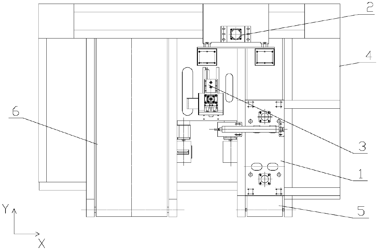
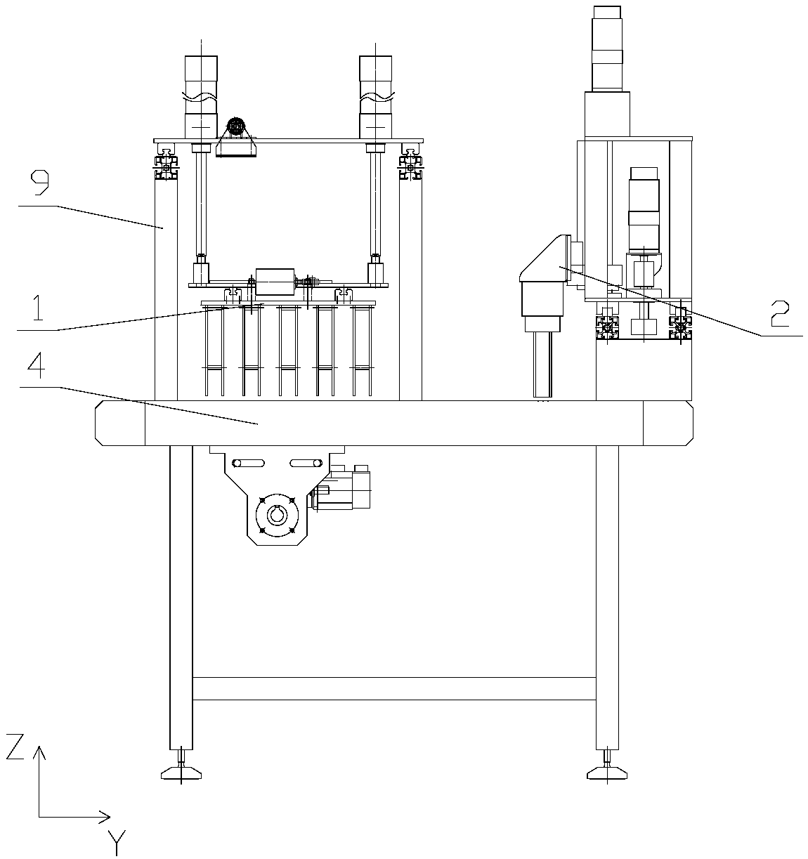
[0035] Such as Figure 1-2 As shown, a kind of current transformer automatic detection experimental equipment provided by the present invention includes a frame 4 and a feeding mechanism 1 arranged on the frame 4, a grabbing mechanism 2, an experimental detection mechanism 3, a feeding conveyor belt 5 and The discharge conveyor belt 6, wherein the feed conveyor belt 5 and the discharge conveyor belt 6 are all arranged along the Y-axis direction, and the experimental detection mechanism 3 is arranged between the feed conveyor belt 5 and the discharge conveyor belt 6 for mutual inductance of the current The feeding mechanism 1 is arranged above the feeding conveyor belt 5 for placing the current transformer on the feeding conveyor belt 5, and the gr...


PUM


Abstract

The invention belongs to the technical field of current transformer detection, and particularly relates to automatic detection experimental equipment for a current transformer. The equipment comprisesa frame, and a feeding mechanism, a grabbing mechanism, an experiment detection mechanism, a feeding conveying belt and a discharging conveying belt which are arranged on the frame. The feeding conveying belt and the discharging conveying belt are both arranged in the Y-axis direction. The experiment detection mechanism is arranged between the feeding conveying belt and the discharging conveyingbelt, and is used for detecting a current transformer. The feeding mechanism is arranged above the feeding conveying belt and is used for placing the current transformer on the feeding conveying belt.The grabbing mechanism is arranged at the end of the feeding conveying belt and the end of the discharging conveying belt and is used for conveying the current transformer between the feeding conveying belt and the experiment detection mechanism and between the experiment detection mechanism and the discharging conveying belt. Manual feeding, wiring and detection can be replaced, operation is easy, the detection result is reliable, the labor cost is reduced, and the detection efficiency and quality are improved.

Description

technical field [0001] The invention belongs to the technical field of current transformer detection, in particular to a current transformer automatic detection experimental equipment. Background technique [0002] With the intensification of market competition, products are required to be updated quickly, with high product quality, and to meet the needs of large and medium batch production and reduce labor intensity. Traditional transformer detection requires manual loading, wiring, and detection, and often requires two people to work together, which is inefficient and causes unfavorable factors such as labor waste. There is an urgent need for high-efficiency and cost-saving automated testing equipment. Contents of the invention [0003] In view of the above problems, the object of the present invention is to provide a current transformer automatic detection experimental equipment to replace manual feeding, wiring and detection, which reduces labor costs and improves the ...

Claims


Application Information

Patent Timeline
Patent Type & Authority Applications(China)
IPC IPC(8): G01R35/02G01R31/01
CPCG01R35/02G01R31/01
Inventor 李涛昌金忠超邵建华高帅张生辉张桂俊赵炳祥董世凯管永秋
Owner DALIAN NORTH INSTR TRANSFORMER GROUP
Why Eureka
Try Eureka