Mechanical gripper

A technology of mechanical grippers and grippers, applied in the field of manipulators, can solve problems such as high cost, inability of manipulators to firmly grasp workpieces, and complicated maintenance

Pending Publication Date: 2020-07-07
ZHAOQING WOSON PRECISION MACHINERY
View PDF0 Cites 3 Cited by
  • Summary
  • Abstract
  • Description
  • Claims
  • Application Information

AI Technical Summary

Problems solved by technology

Among them, the pick-and-place of large workpieces is almost always operated by manipulators. In order to achieve a better grasping effect, smart manipulators are generally required, but smart manipulators involve many joints in activities, and often require program control, which is expensive and complicated to maintain. The non-intelligent manipulators on the market, because they mainly rely on mechanical transmission, often cannot make multiple changes to adapt to workpieces of different specifications, resulting in the need to manufacture different types of manipulators according to different workpieces, or the situation that the manipulator cannot firmly grasp the workpiece.

Method used


Image

  • Mechanical gripper
  • Mechanical gripper
  • Mechanical gripper

Examples


Embodiment Construction

[0035] The accompanying drawings are for illustrative purposes only, and should not be construed as limitations on this patent; in order to better illustrate this embodiment, certain components in the accompanying drawings will be omitted, enlarged or reduced, and do not represent the size of the actual product; for those skilled in the art It is understandable that some well-known structures and descriptions thereof may be omitted in the drawings.

[0036] In the description of the present invention, it should be noted that unless otherwise specified and limited, the terms "installation" and "connection" should be understood in a broad sense, for example, it can be a fixed connection, a detachable connection, or an integral Ground connection; it can be a mechanical connection or an electrical connection; it can be a direct connection or an indirect connection through an intermediary. It can be said that the internal communication of two components. Those of ordinary skill in ...


PUM


Abstract

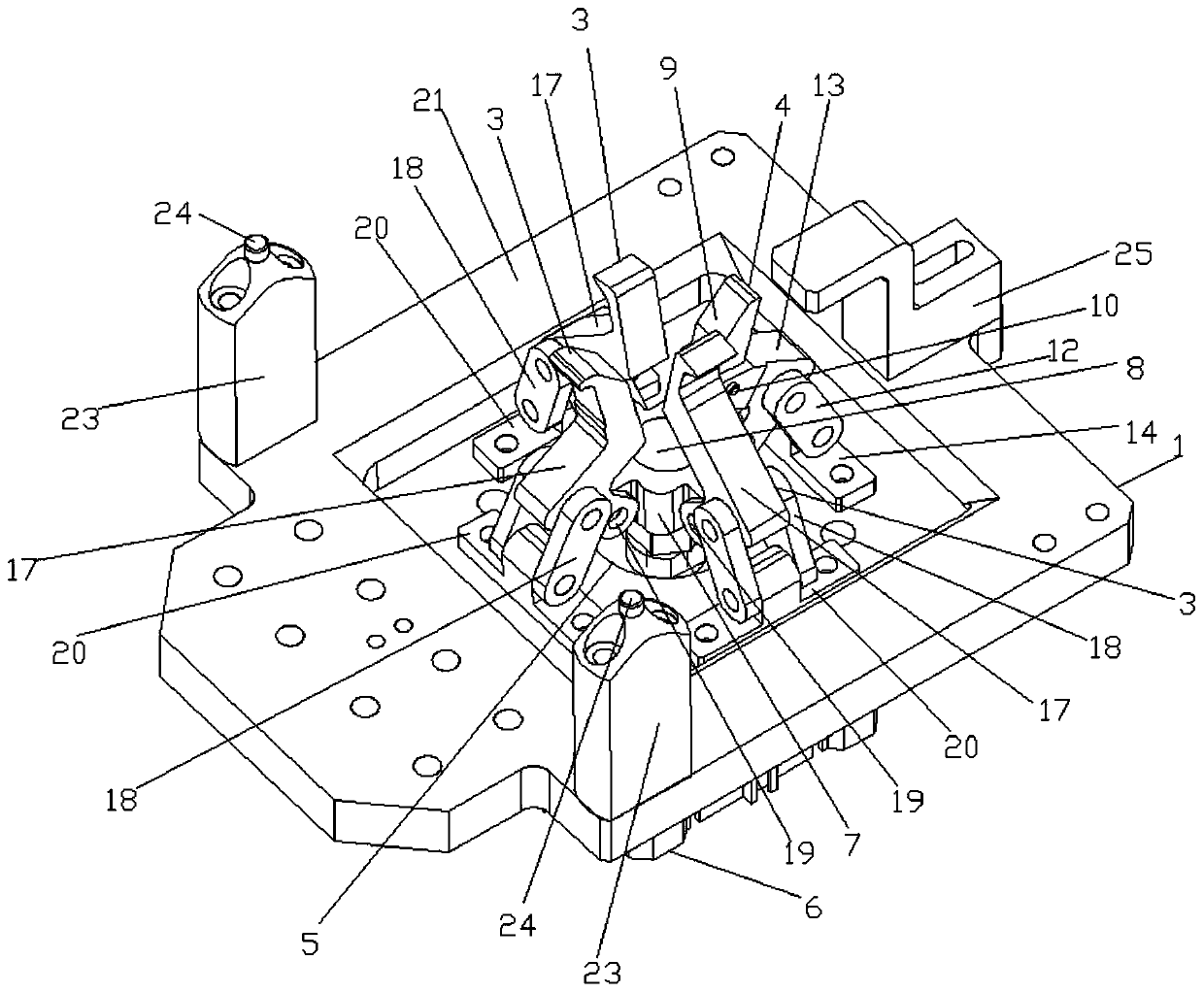
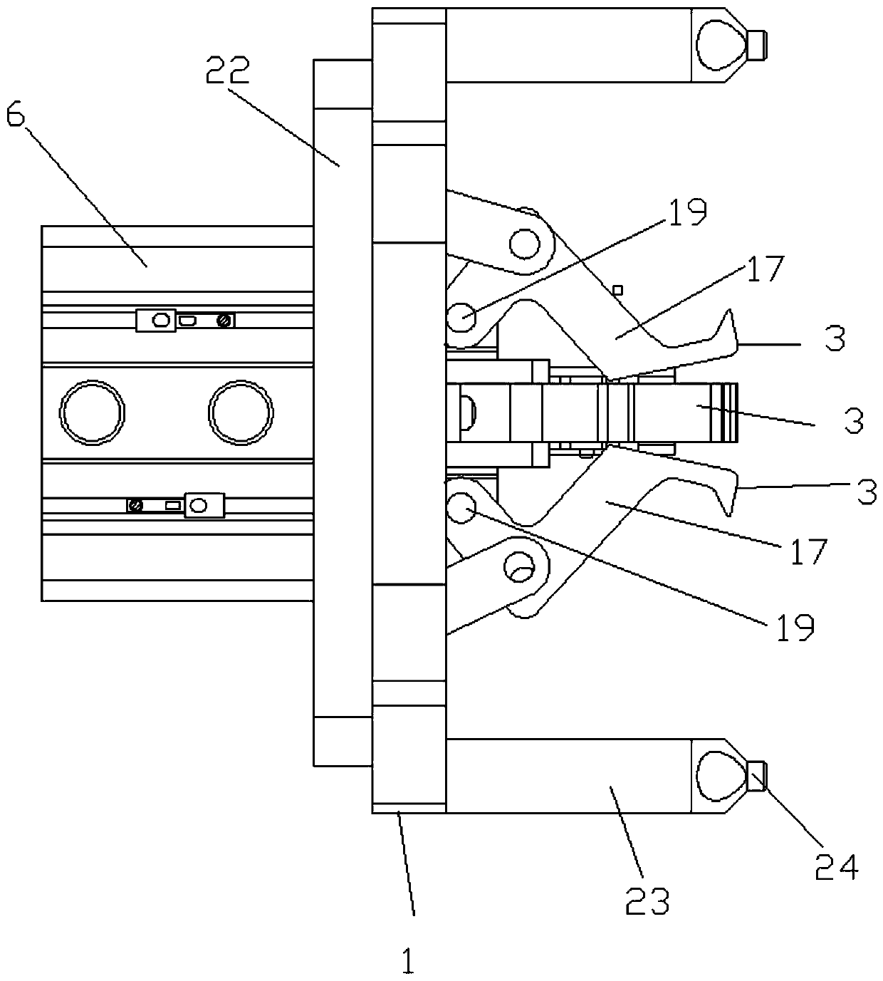
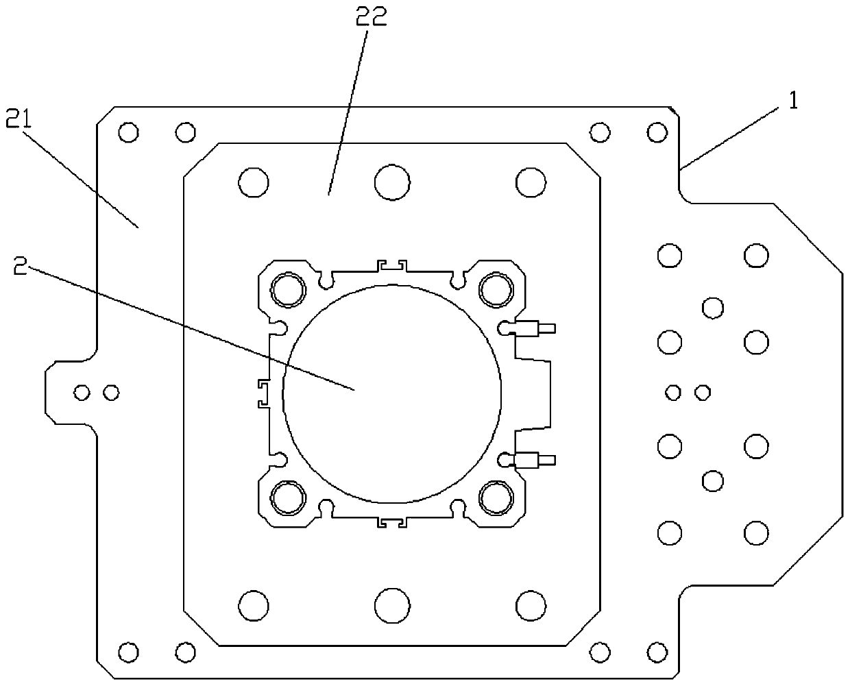
The invention relates to the field of robots, in particular to a mechanical gripper. The mechanical gripper comprises a clamping fixing seat, a clamping transmission air cylinder and fixing clamping grippers, and further comprises a movable clamping device; the clamping fixing seat is provided with a through hole, and the clamping transmission air cylinder movably sleeves the through hole; and thefixing clamping grippers and the movable clamping device are distributed on the outer side of the through hole and are connected with the clamping transmission air cylinder, and when the clamping transmission air cylinder extends, the fixing clamping grippers and the movable clamping device are correspondingly movably stretch outside to clamp a workpiece. According to the mechanical gripper, thestretching force formed by the transmission air cylinder is uniformly transmitted to the fixing clamping grippers and the movable clamping device, the fixing clamping grippers firstly can press the workpiece to a certain degree, the movable clamping device can automatically adjust according to the specific shape of the workpiece, the workpiece is further pressed, and finally the mechanical grippercan apply the matched grabbing force according to various different specifications of workpieces so as to stably remove the workpiece.

Description

technical field [0001] The present invention relates to the field of manipulators, more specifically, to a manipulator gripper. Background technique [0002] With the rapid development of science and technology, people's living standards continue to improve, resulting in an increase in labor costs. At the same time, more and more manufacturing industries are increasingly moving towards mechanical automation and even intelligent development models. Among them, the pick-and-place of large workpieces is almost always operated by manipulators. In order to achieve a better grasping effect, smart manipulators are generally required, but smart manipulators involve many joints in activities, and often require program control, which is expensive and complicated to maintain. Non-intelligent manipulators on the market rely mainly on mechanical transmission, and often cannot make multiple changes to adapt to workpieces of different specifications, resulting in the need to manufacture di...

Claims


Application Information

Patent Timeline
Patent Type & Authority Applications(China)
IPC IPC(8): B25J15/00B25J15/10
CPCB25J15/00B25J15/10
Inventor 李仕标区兴盛
Owner ZHAOQING WOSON PRECISION MACHINERY
Why Eureka
Try Eureka