
Feeding clamp and injection molding stamping equipment with same

A technology for clips and processing equipment, applied in electrical components, semiconductor/solid-state device manufacturing, circuits, etc., can solve problems such as restricting the development of intelligent equipment and low production efficiency

Pending Publication Date: 2020-07-07
深圳市远望工业自动化设备有限公司
View PDF0 Cites 0 Cited by
  • Summary
  • Abstract
  • Description
  • Claims
  • Application Information

AI Technical Summary

Problems solved by technology

[0003] With the development of technology, the miniaturization and multi-function of electronic products have become the main development direction. The miniaturization of electronic products requires semiconductor devices not only to be smaller in size, but also to ensure their structural strength and anti-pollution and anti-corrosion performance. Therefore, injection molding packaging is required. However, in the prior art, manual feeding is still required for injection molding, and the production efficiency is low, which greatly restricts the development of smart devices. Therefore, it is necessary to provide a simple and compact structure and convenient feeding. The feeding fixture has become a problem that must be solved at present

Method used


Image

  • Feeding clamp and injection molding stamping equipment with same
  • Feeding clamp and injection molding stamping equipment with same
  • Feeding clamp and injection molding stamping equipment with same

Examples


Embodiment Construction

[0036] The present invention will be described in detail below in conjunction with the accompanying drawings and embodiments. It should be noted that, if there is no conflict, the embodiments of the present invention and various features in the embodiments can be combined with each other, and all are within the protection scope of the present invention.

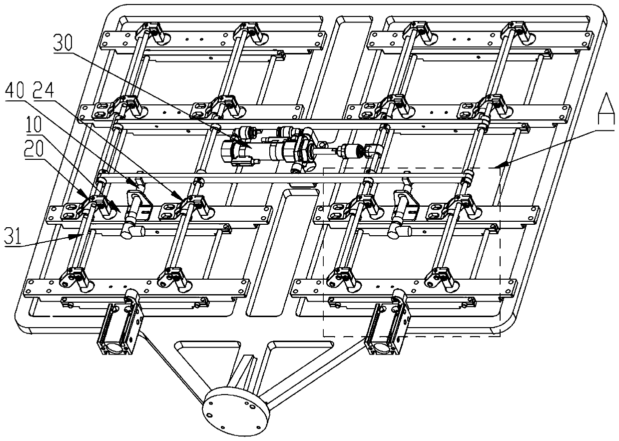
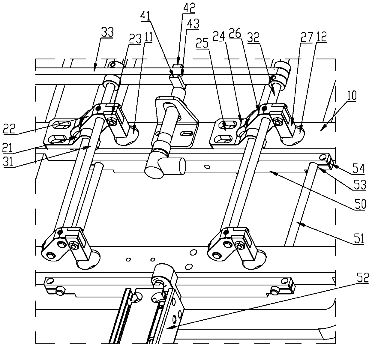
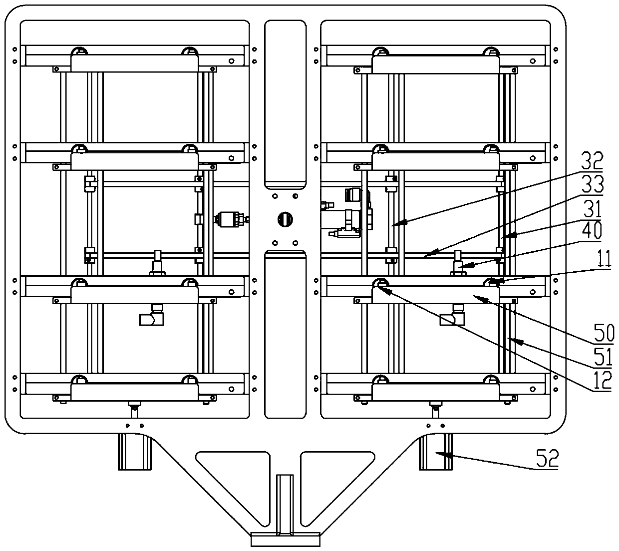
[0037] see Figure 1 to Figure 3 , the invention discloses a loading fixture, which includes:

[0038] The first fixing seat 10 is provided with a first feeding hole 11;

[0039] The first knocking assembly 20 is connected with the first fixing seat 10 and is used for knocking the first material inserted in the first feeding hole 11 into the processing equipment;

[0040] The first transmission rod 31 is connected to the first knocking assembly 20;

[0041] The first driving mechanism 30 is connected with the first knocking assembly 20 through the first transmission rod 31, and is used to drive the first knocking assembly ...


PUM


Abstract

The invention discloses a feeding clamp and injection molding stamping equipment with the same. The feeding clamp comprises a first fixing seat, a first knocking assembly, a first transmission rod anda first driving mechanism; the first fixing seat is provided with a first feeding hole; the first knocking assembly is connected with the first fixing seat and used for impacting a first material inserted into the first feeding hole into processing equipment; the first transmission rod is connected with the first knocking assembly; and the first driving mechanism is connected with the first knocking assembly through the first transmission rod and used for driving the first knocking assembly to impact the first material so as to impact the first material into the processing equipment. The feeding clamp has the advantages of simple and compact structure, convenient feeding, high compatibility, good synchronization performance, low maintenance cost and high production efficiency.

Description

technical field [0001] The invention relates to the technical field of injection molding, in particular to a material loading fixture and injection molding stamping equipment with the material loading fixture. Background technique [0002] A semiconductor device is an electronic device whose conductivity is between a good conductor and an insulator. It uses the special electrical properties of semiconductor materials to complete specific functions. It can be used to generate, control, receive, transform, amplify signals and perform energy conversion. [0003] With the development of technology, the miniaturization and multi-function of electronic products have become the main development direction. The miniaturization of electronic products requires semiconductor devices not only to be smaller in size, but also to ensure their structural strength and anti-pollution and anti-corrosion performance. Therefore, injection molding packaging is required. However, in the prior art, ...

Claims


Application Information

Patent Timeline
IPC IPC(8): B29C45/14H01L21/67H01L21/687
CPCB29C45/14008B29C45/14647H01L21/67126H01L21/687
Inventor 龙超祥
Owner 深圳市远望工业自动化设备有限公司
Learn More