

Processing device for splicing-type coil
A processing device and splicing technology, applied in the direction of winding strip, thin material processing, transportation and packaging, etc., can solve the problems of disconnection and falling off, affecting the normal use of automatic placement machines, etc.
- Summary
- Abstract
- Description
- Claims
- Application Information
AI Technical Summary
Problems solved by technology
Method used
Image

Examples
Embodiment 1
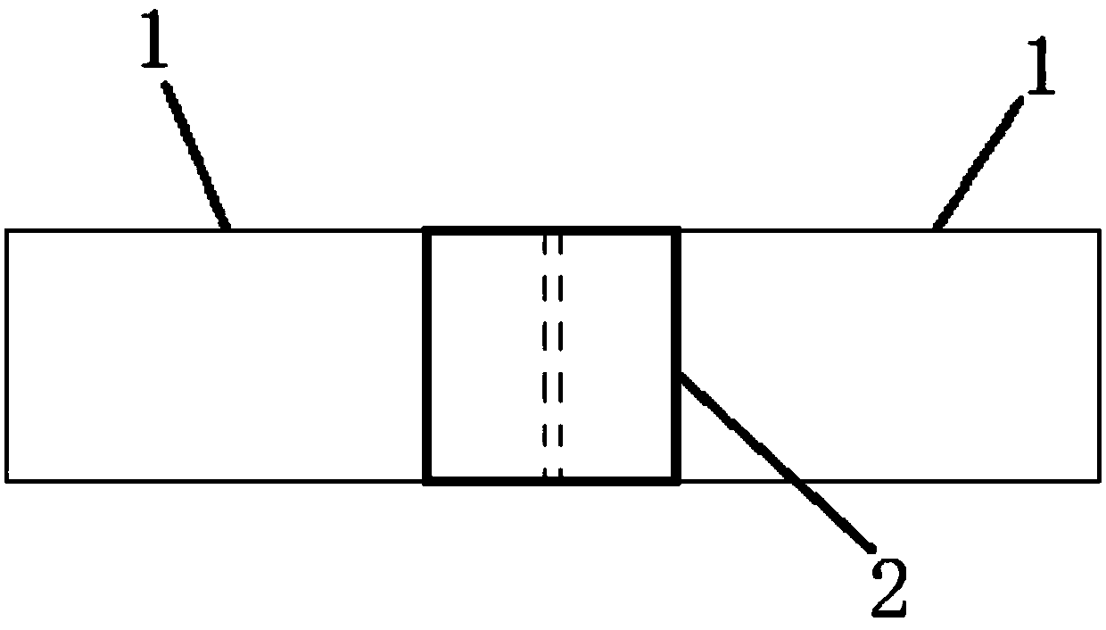
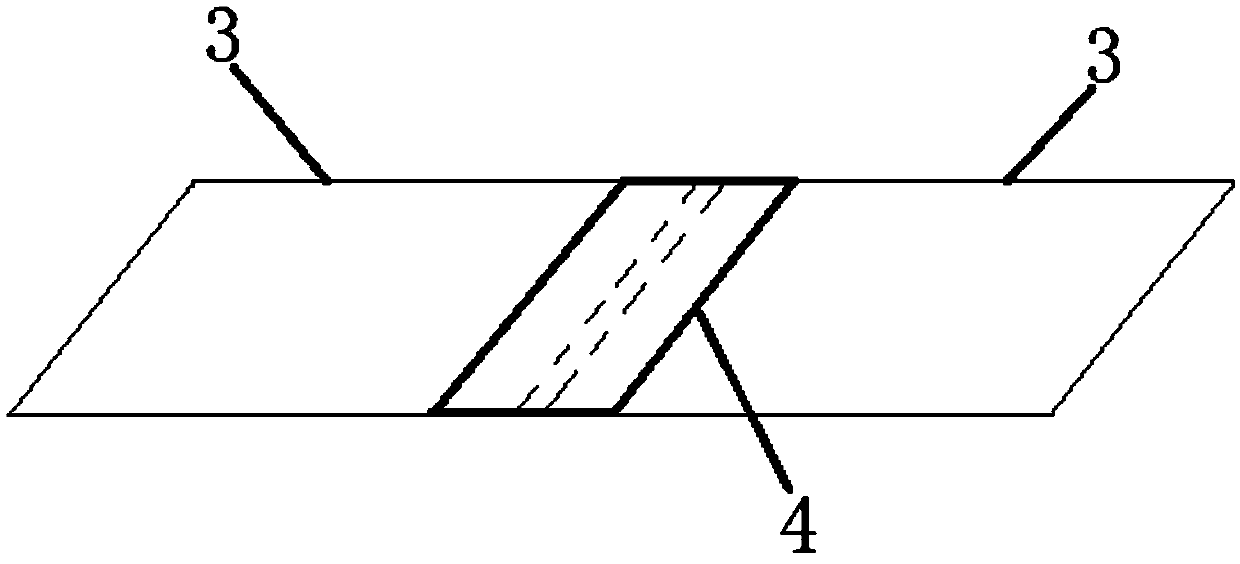
[0025] Such as figure 2 The spliced coil material shown includes a plurality of parallelogram strips 3 connected end to end in sequence and a parallelogram adhesive tape 4 arranged between two adjacent parallelogram strips 3. In the parallelogram strips 3, two adjacent sides The included angle between them is 45°; in the parallelogram tape 4, the included angle between two adjacent sides is 45°.
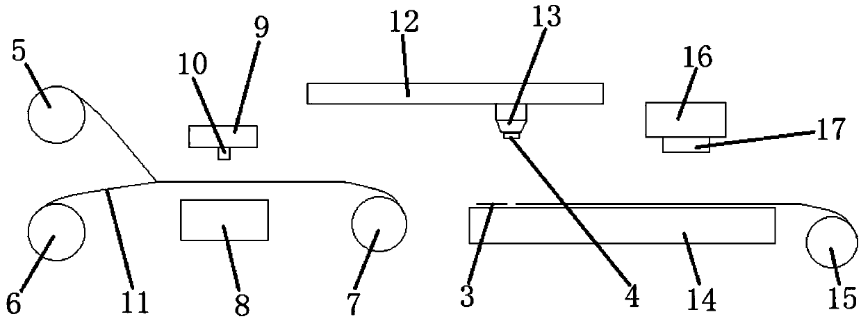
[0026] Such as image 3 The shown splicing coil material processing device includes a tape cutting mechanism, a tape laminating mechanism and a material belt conveying mechanism. between two adjacent parallelogram strips 3 .
[0027] Wherein, tape cutting mechanism comprises tape feed roller 5, is arranged on the release film feed roller 6 below tape feed roller 5, release film receiving roller 7 that is adapted to release film feed roller 6 and is arranged on the release film The cutting tape assembly between the feeding roller 6 and the release film receiving roller 7. Tape ...
Embodiment 2
[0032] In this embodiment, in the parallelogram strip 3 , the angle between two adjacent sides is 60°; in the parallelogram tape 4 , the angle between two adjacent sides is 60°. A release film 11 is provided between the release film feeding roller 6 and the release film receiving roller 7, and the bottom of the adhesive tape cutting knife 10 is provided with a blade, and the length direction of the blade is 60° to the length direction of the release film 11. angle. All the other are with embodiment 1.
Embodiment 3
[0034] In this embodiment, in the parallelogram strip 3 , the angle between two adjacent sides is 30°; in the parallelogram tape 4 , the angle between two adjacent sides is 30°. A release film 11 is provided between the release film feeding roller 6 and the release film receiving roller 7, and the bottom of the adhesive tape cutting knife 10 is provided with a blade, and the length direction of the blade is 30° to the length direction of the release film 11. angle. All the other are with embodiment 1.
PUM
 Abstract
Description
Claims
Application Information