Furnace roller and combustion furnace grate

A technology of furnace rollers and steel pipes, which is applied in the field of waste treatment equipment and can solve problems such as deformation

Pending Publication Date: 2020-07-07
东莞东燃热能科技股份有限公司
View PDF0 Cites 0 Cited by
  • Summary
  • Abstract
  • Description
  • Claims
  • Application Information

AI Technical Summary

Problems solved by technology

[0004] The purpose of the present invention is to provide a furnace roll, aiming to solve the technical problem in the prior art that the furnace roll is deformed due to its long-term operation under high temperature conditions

Method used


Image

  • Furnace roller and combustion furnace grate
  • Furnace roller and combustion furnace grate
  • Furnace roller and combustion furnace grate

Examples


Embodiment Construction

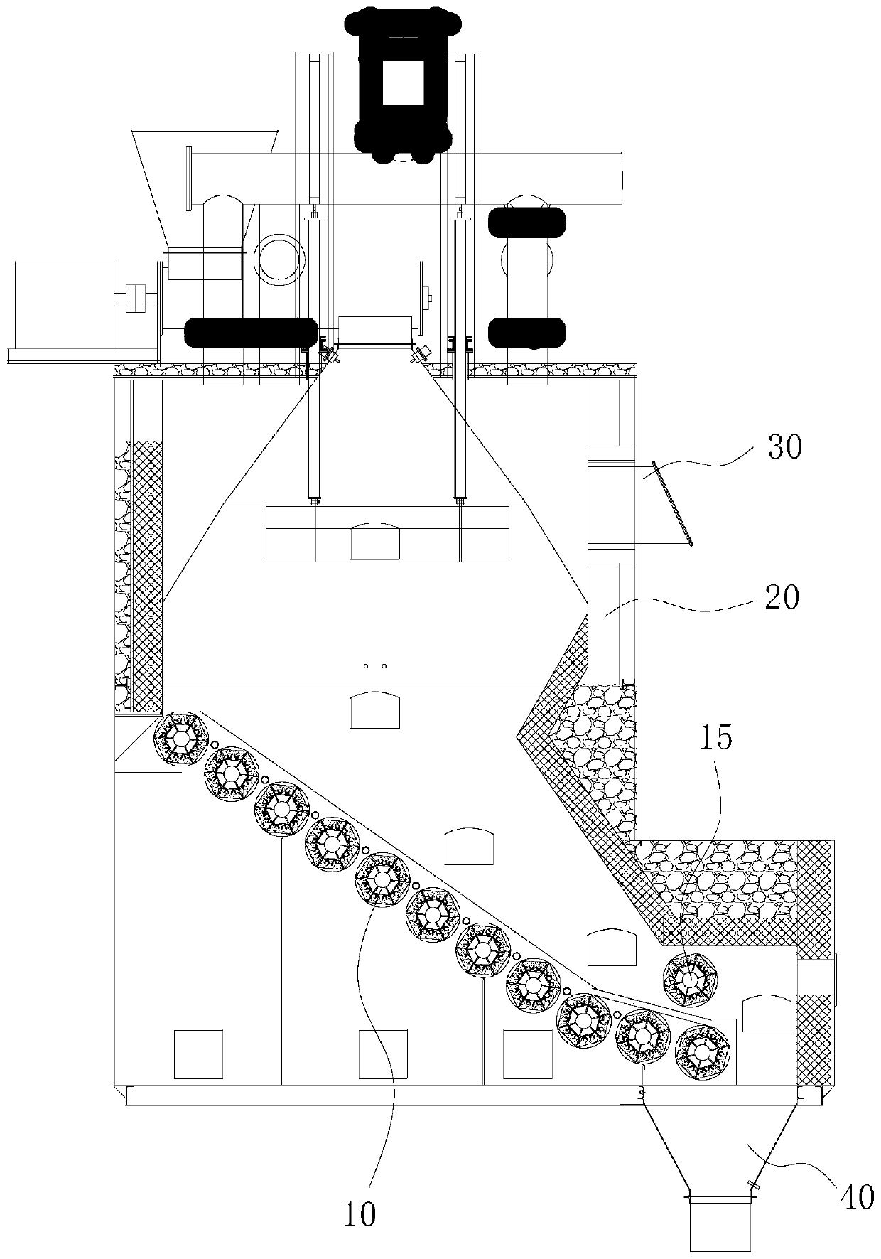
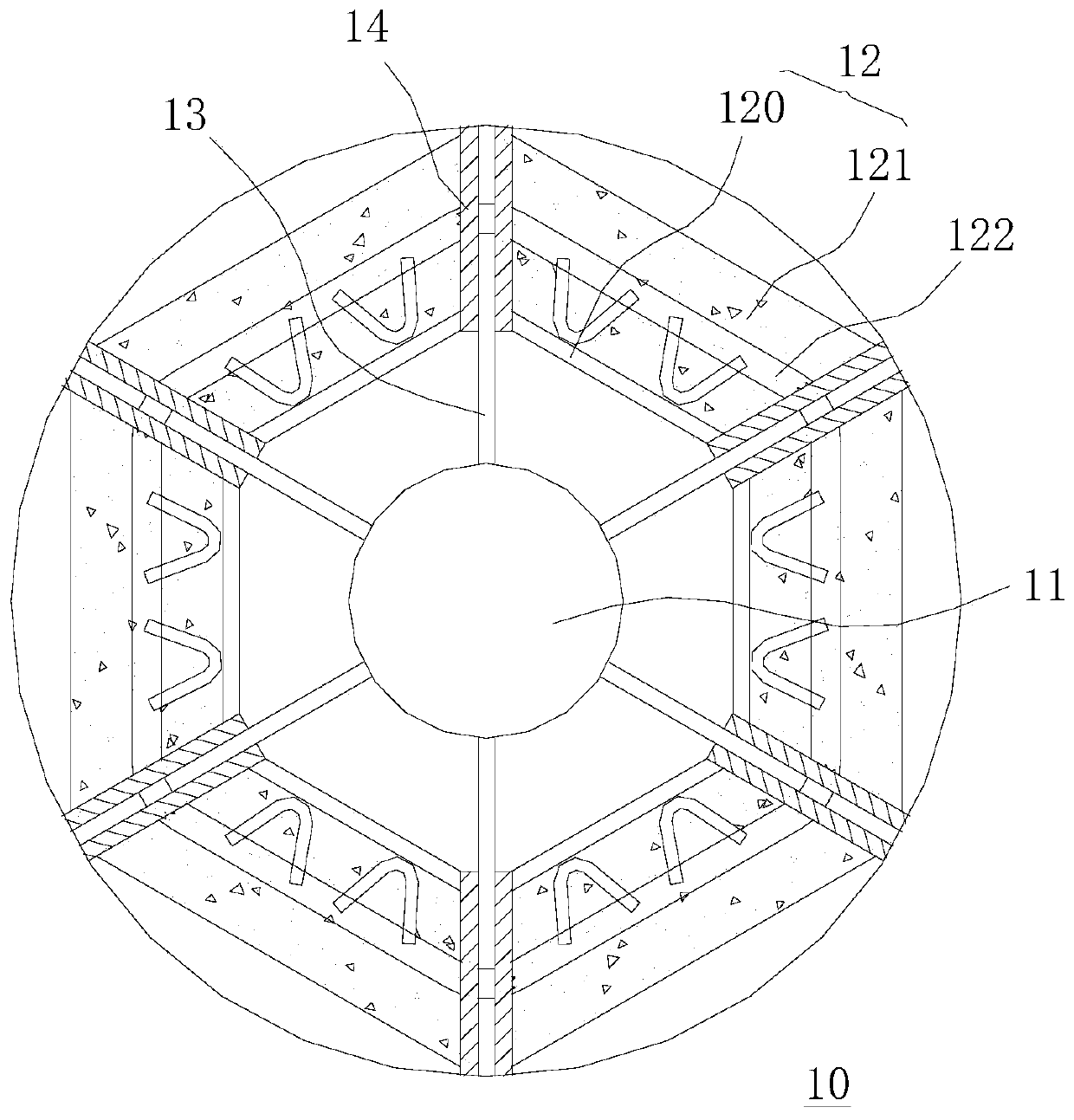
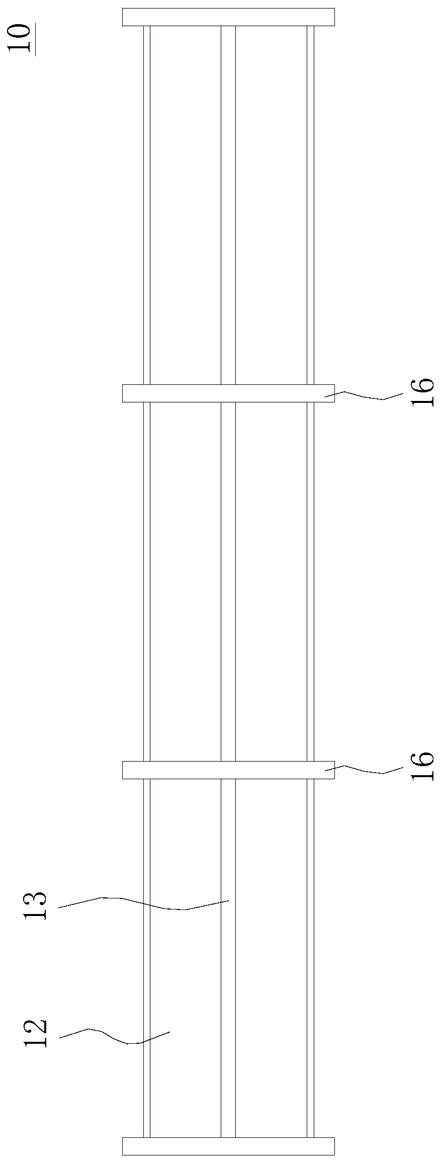
[0027] Embodiments of the present invention are described in detail below, examples of which are shown in the drawings, wherein the same or similar reference numerals designate the same or similar elements or elements having the same or similar functions throughout. Attached below by reference Figure 1~3 The described embodiments are exemplary, and are intended to explain the embodiments of the present invention, and should not be construed as limitations of the present invention.

[0028] In the description of the embodiments of the present invention, it should be understood that the terms "length", "width", "upper", "lower", "front", "rear", "left", "right", "vertical ", "horizontal", "top", "bottom", "inner", "outer" and other indicated orientations or positional relationships are based on the orientations or positional relationships shown in the drawings, and are only for the convenience of describing the embodiments of the present invention and simplifying Describes, bu...


PUM


Abstract

The invention belongs to the technical field of waste disposal equipment, and relates to a furnace roller and a combustion furnace grate. The furnace roller comprises a steel pipe, wherein a thermal insulating layer is arranged on the outer circumference of the steel pipe, a plurality of steel plates pass through the thermal insulating layer and then are connected with the steel pipe, and a bufferlayer is arranged between the steel plates and the thermal insulating layer so as to reduce the condition of extrusion caused by high-temperature expansion between the steel plates and the thermal insulating layer. When the furnace roller is at high temperature, the steel plates and the thermal insulating layer expand due to heating, the buffer layer is extruded after the steel plates and the thermal insulating layer expand, the buffer layer has elastic performance, the buffer layer elastically deforms within the elastic range after being extruded by the steel plates and the thermal insulating layer, so that the condition of collision damage due to direct contact after the steel plates and the thermal insulating layer expand is avoided, the stability of the furnace roller at high temperature is increased, the structure is stable, the service life is long, and the safety performance is high.

Description

technical field [0001] The invention belongs to the technical field of waste treatment equipment, and in particular relates to a furnace roller and a combustion furnace grate. Background technique [0002] With the improvement of people's living standards, more and more domestic garbage is produced in daily life, and the content of non-degradable components is also increasing, and the pollution to the environment is increasing day by day. The currently recognized best disposal method is centralized waste incineration for power generation, which has high investment costs and large processing capacity, and is generally used in large and medium-sized cities with large populations. For towns and vast rural areas with a small population and relatively low domestic waste production, long-distance transshipment is required, and the cost of infrastructure construction and transshipment is very high. [0003] Therefore, for the vast towns and rural areas with low population density,...

Claims


Application Information

Patent Timeline
Patent Type & Authority Applications(China)
IPC IPC(8): F23H13/08F23G5/00F23G5/027
CPCF23G5/002F23G5/027F23G2201/10F23G2201/40F23G2203/103F23H13/08F23H2700/009F23J1/06
Inventor 晏志勇
Owner 东莞东燃热能科技股份有限公司
Why Eureka
Try Eureka